
0102030405

Double-Sided Impedance FPC | High-Speed Signal Transmission | Display Connector Solution


Produet Manufacturing Instructions
|
Type |
Double-sided FPC,impedance |
Silkscreen color |
white(GTO,GBO) |
|
Materia |
panasonic RF775、Polyimide、TG320 non adhesive rolled copper |
Via treatment |
coverlay over via |
|
Number of layer |
2L |
Density of mechanical drilling hole |
2W/㎡ |
|
Board Thickness |
0.2mm |
Drilling times |
1 time |
|
Single size |
168*117mm/2PCS |
Min via size |
0.25mm |
|
Surface finish |
ENIG |
Min line width/space |
4/4mil |
|
Inner copper thickness |
/ |
Aperture ratio |
1mil |
|
Outer copper thickness |
35um |
Pressing times |
/ |
|
Color of solder mask |
yellow coverlay |
PN |
B0289181B |
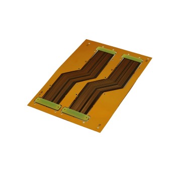
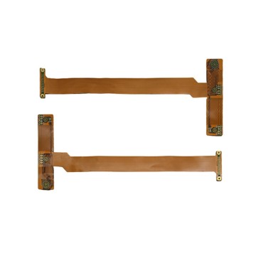
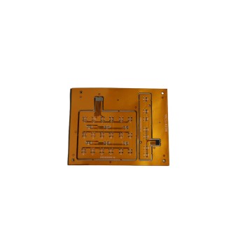
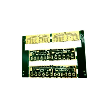
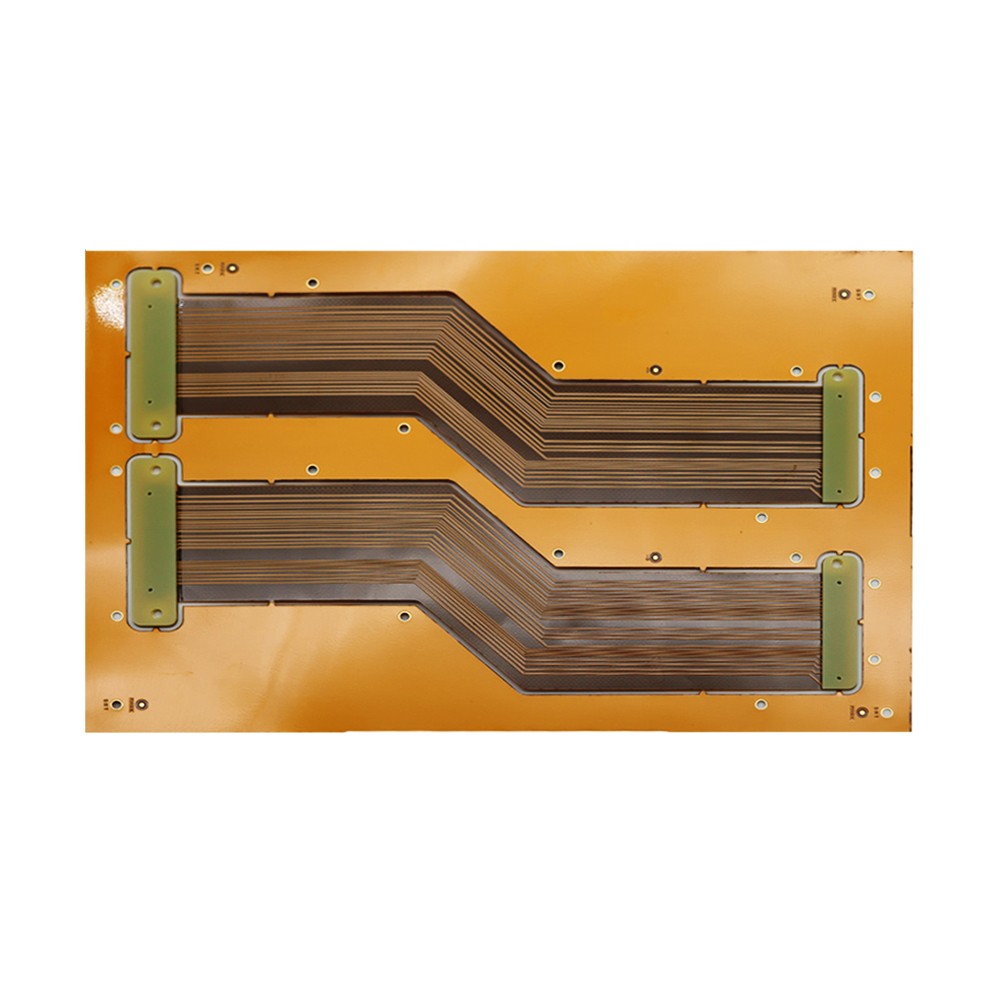
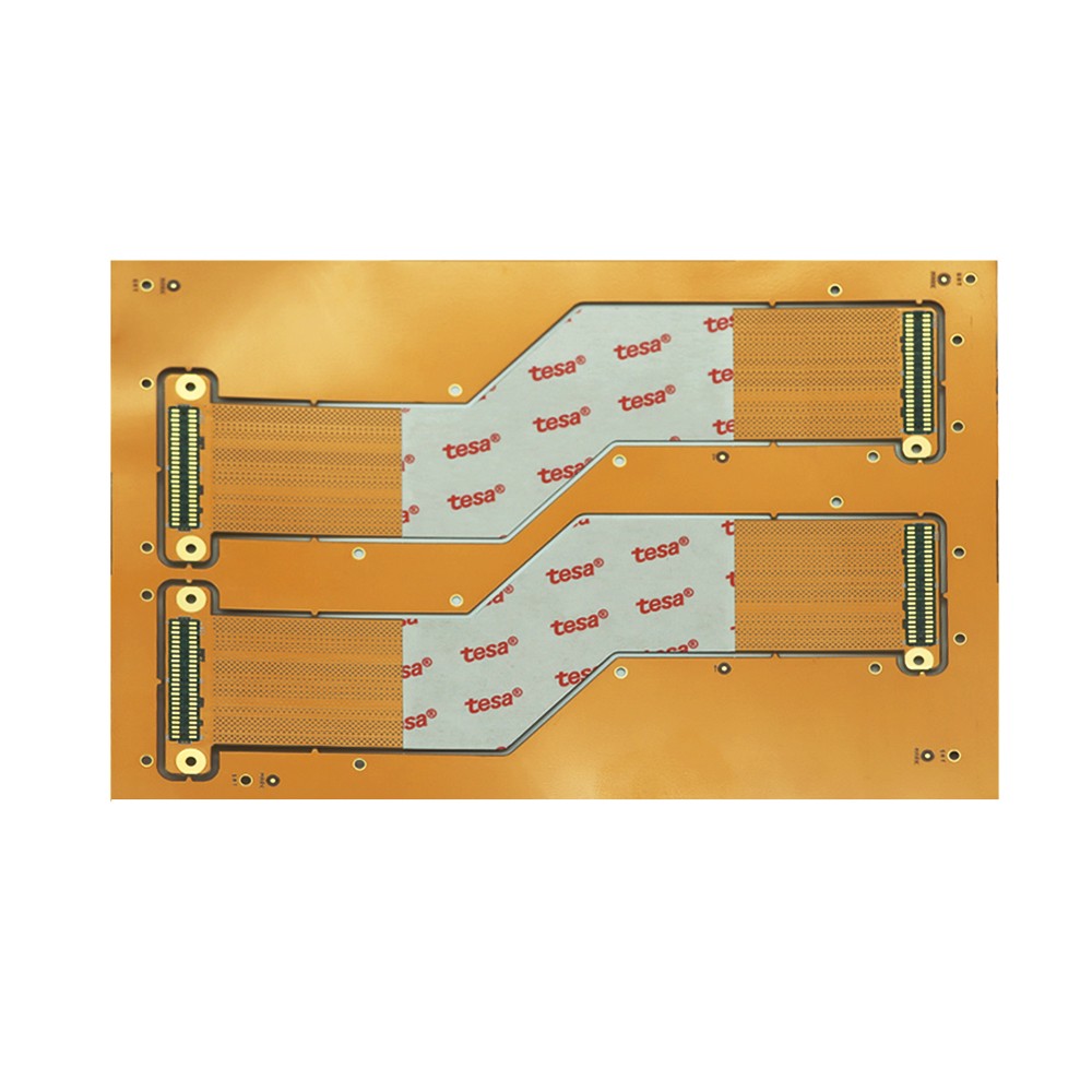
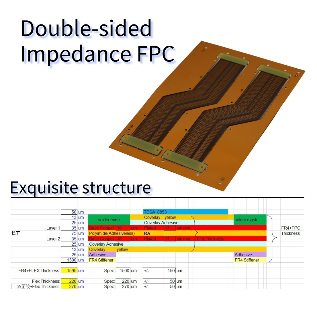
Double-sided Impedance FPC: FPC for Display Connection
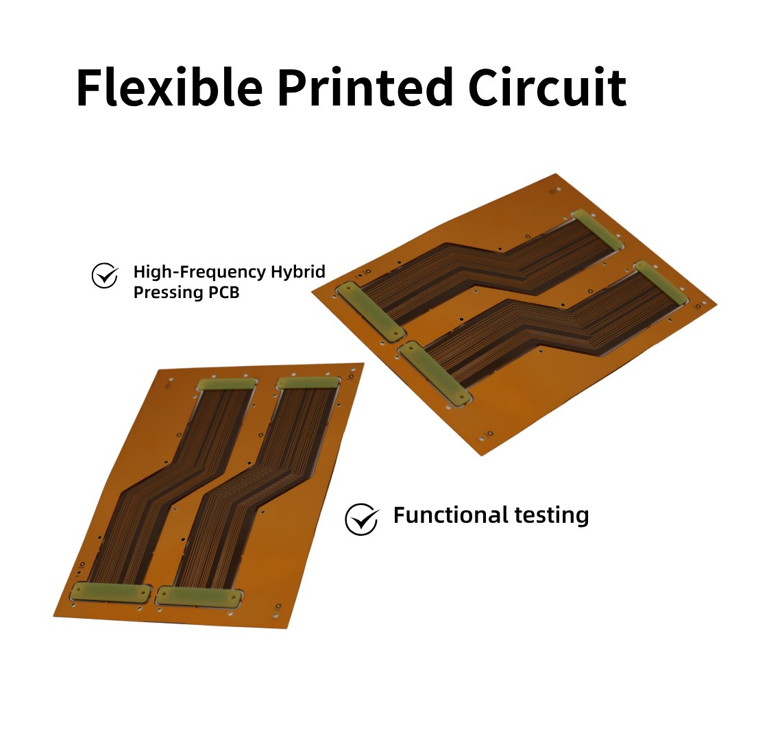
This double-sided impedance FPC is specifically designed for display connectors. It serves as a crucial bridge connecting the motherboard and the display, and is responsible for accurately transmitting video and touch signals.
It is made of Panasonic RF775, polyimide, and TG320 non-adhesive rolled copper, ensuring excellent electrical and mechanical properties.
With a two-layer board structure, it is only 0.2mm thick, which is thin and lightweight while meeting the electrical requirements.
The single-piece size is 168117mm, and there are 2 pieces per batch, making it suitable for various devices.
The surface is treated with ENIG, which provides strong anti-oxidation properties and excellent solderability.
The outer copper thickness is 35um, ensuring stable signal transmission.
The yellow solder mask is paired with white silk screen printing, which is convenient for identification.
The vias are covered with a coverlay. The density of mechanical drilling holes is 2W/㎡, the minimum via size is 0.25mm, and the minimum line width/line spacing is 4/4mil. All these parameters are precise, making it a high-quality FPC that ensures the efficient operation of the display.
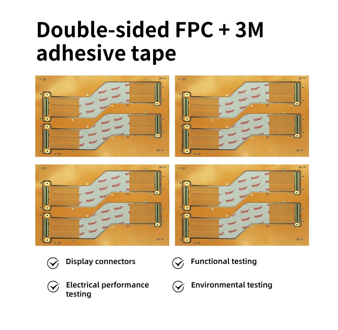
To detect the signal transmission quality of the FPC used in display connectors, it can be started from the following aspects:
1.Electrical Performance Testing
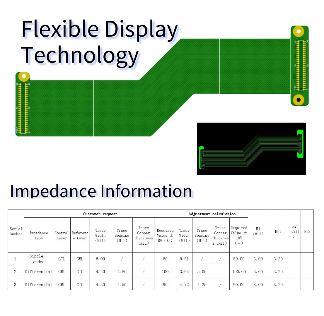
● Impedance Testing: Use a high-precision impedance analyzer, such as a network analyzer, to measure the circuit impedance of the FPC. Connect the test probes to the designated test points of the FPC, and measure the single-ended impedance and differential impedance, ensuring that their values are within the range of ±10% of the design specifications. For example, if the designed single-ended impedance is 50Ω, the measured value should be between 45Ω and 55Ω.
● Continuity Testing: Use a continuity tester to detect the continuity of the FPC circuits. Connect the probes of the tester to both ends of the circuit and check for any open circuits, short circuits, or poor contacts. For FPCs with multiple circuits, an Automatic Test Equipment (ATE) can be used for batch testing to improve the testing efficiency.
● Insulation Resistance Testing: Use an insulation resistance tester to measure the insulation resistance between the FPC circuits and between the circuits and the grounding layer. Apply the test voltage to the corresponding circuits and measure the resistance value. Generally, the insulation resistance is required to be greater than a certain threshold, such as over 100MΩ.
2.Signal Integrity Testing
● Eye Diagram Testing: Use a high-speed oscilloscope and the corresponding probes to perform eye diagram testing on the signals transmitted by the FPC. Connect the signal source to the input end of the FPC, collect the signals at the output end and display the eye diagram. Evaluate the signal quality by observing parameters such as the eye opening, rise time, and fall time of the eye diagram. A good eye diagram should have a clear open part, short rise and fall times, and small jitter.
● Jitter Testing: Use a specialized jitter analyzer to measure the jitter of the signals during transmission. Jitter refers to the timing error of the signals, and excessive jitter will affect the correct reception of the signals. Analyze the amplitude and frequency components of the jitter to determine the degree of influence of the FPC on the signal jitter.
● Crosstalk Testing: For FPCs with multiple parallel circuits, crosstalk testing is required. Use a network analyzer or other crosstalk testing equipment to measure the crosstalk level between adjacent circuits. By adjusting the test conditions, such as the signal frequency and transmission rate, evaluate the crosstalk resistance of the FPC under different working environments.
3.Functional Testing
● Simulated Real Application Testing: Connect the FPC to the actual display and motherboard, and conduct tests simulating real applications. By inputting different video signals and touch signals, observe whether the display effect of the display and the touch response are normal. Check for any problems such as image distortion, abnormal color, and insensitive touch.
● Durability Testing: Perform multiple bending, folding, and plugging/unplugging tests on the FPC to simulate the mechanical stress it will experience in actual use. After each test, repeat the above electrical performance and functional tests to check whether the signal transmission quality is affected. By evaluating the change in the signal transmission quality of the FPC after a certain number of mechanical stress tests, determine its durability and reliability.
4.Environmental Testing
● Temperature Testing: Place the FPC in a high and low temperature test chamber and conduct cyclic tests according to the specified temperature range and time. For example, from -40°C to 85°C, keep it at each temperature point for a certain period (such as 2 hours), and then let it recover at room temperature for a while. Before and after the test, conduct electrical performance and functional tests to check whether the signal transmission quality is affected by the temperature change.
● Humidity Testing: Place the FPC in a humidity test chamber and set certain humidity conditions (such as 90% RH) and time (such as 48 hours) for the test. After the test is completed, conduct electrical performance and functional tests to evaluate the impact of humidity on the signal transmission quality.
FAQ – Frequently Asked Questions
What are the Most Common Errors in Flexible Circuit Design?
1: Ignoring the Bending Radius
In the design of flexible printed circuits (FPCs), due to the special characteristics of flexible circuits (such as bendability, thinness and lightness, material properties, etc.), some common errors are likely to occur during the design process. The following are some of the most common errors and their solutions:
1: Ignoring the Bending Radius
Error: Failure to consider the minimum bending radius of the material, resulting in the FPC breaking or delaminating when bent.
Solution: Calculate the minimum bending radius (usually 6 to 10 times the thickness of the base material) according to the thickness of the base material and the material properties.
Mark the bending area clearly in the design, and avoid arranging components or vias in the bending area.
Solution: Calculate the minimum bending radius (usually 6 to 10 times the thickness of the base material) according to the thickness of the base material and the material properties.
Mark the bending area clearly in the design, and avoid arranging components or vias in the bending area.
Error: The routing layout is too concentrated or the routing direction is unreasonable, resulting in mechanical stress concentration or signal interference.
Solution: Use arc-shaped routing in the bending area to avoid right-angle turns.
Disperse the routing layout to avoid stress concentration in a certain area.
Adopt differential pair design for high-frequency signal routing to reduce crosstalk.
Disperse the routing layout to avoid stress concentration in a certain area.
Adopt differential pair design for high-frequency signal routing to reduce crosstalk.
3: Improper Impedance Control
Error: Failure to consider impedance matching, resulting in reflections or losses during high-frequency signal transmission.
Solution: Calculate the routing width, spacing, and dielectric constant according to the signal frequency and material properties to ensure impedance matching.
Use simulation tools to verify the impedance design.
4: Inadequate Thermal Management
Error: Failure to consider the thermal conductivity performance of the FPC, resulting in local overheating or thermal stress concentration.
Solution: Design heat dissipation paths around the heat-generating components, such as thermal vias or high thermal conductivity materials.
Optimize the layout of components to avoid heat concentration.
5: Improper Material Selection
Error: The selected base material, copper foil, or adhesive does not meet the application requirements, resulting in insufficient performance or failure.
Error: The thickness or material selection of the cover layer is inappropriate, resulting in insufficient flexibility of the FPC or poor protection effect.
Solution: Select appropriate cover layer materials and thicknesses according to the application requirements.
Use thinner cover layers in the bending area to improve flexibility.
9: Insufficient Simulation Verification
Error: Failure to conduct simulation verification after the design is completed, resulting in the actual performance not meeting the standards.
Solution: Use simulation tools to verify signal integrity, thermal management, and mechanical strength.
Conduct multiple iterative optimizations in the early stage of the design.
10: Ignoring Manufacturing Process Limitations
Error: The design does not consider the limitations of the manufacturing process, resulting in a low yield rate or inability to produce.
Solution: Communicate closely with the manufacturer to understand the process limitations (such as minimum line width, line spacing, via diameter, etc.).
Consider the manufacturing feasibility in the design stage and avoid overly complex designs.
11: Unreasonable Grounding Design
Error: The grounding design is incomplete or unreasonable, resulting in signal interference or EMI problems.
Solution: Design a complete grounding layer to ensure a good return path for high-frequency signals.
Optimize the layout of the grounding layer and power layer in multi-layer FPCs.
12: Failure to Consider Environmental Factors
Error: Failure to consider the performance of the FPC in high-temperature, high-humidity, or chemical environments, resulting in failure.
Solution: Select appropriate materials and surface treatment processes according to the application environment.
Conduct environmental tests (such as high-temperature, damp heat, salt spray tests) to verify reliability.
13: Unreasonable Component Layout
Optimize the layout of components to avoid heat concentration.
5: Improper Material Selection
Error: The selected base material, copper foil, or adhesive does not meet the application requirements, resulting in insufficient performance or failure.
Solution: Select appropriate materials according to the application scenarios (such as temperature, number of bends, signal frequency, etc.).
Select rolled annealed copper foil (RA) and highly flexible base materials (such as PI) for dynamic bending applications.
6: Unreasonable Interlayer Connection Design
Error: The interlayer connection design of multi-layer FPCs is inappropriate, resulting in poor signal integrity or insufficient mechanical strength.
Solution: Design vias and blind vias reasonably to ensure reliable interlayer connections.
Add reinforcing plates in the interlayer connection area to improve mechanical strength.
7: Failure to Consider Dynamic Stress
Error: In dynamic bending applications, failure to optimize the routing layout and material selection leads to a shortened lifespan of the FPC.
8: Improper Cover Layer Design6: Unreasonable Interlayer Connection Design
Error: The interlayer connection design of multi-layer FPCs is inappropriate, resulting in poor signal integrity or insufficient mechanical strength.
Solution: Design vias and blind vias reasonably to ensure reliable interlayer connections.
Add reinforcing plates in the interlayer connection area to improve mechanical strength.
7: Failure to Consider Dynamic Stress
Error: In dynamic bending applications, failure to optimize the routing layout and material selection leads to a shortened lifespan of the FPC.
Solution: Use serpentine routing or arc-shaped routing in the dynamic bending area to disperse the stress.
Select highly flexible materials and adhesives.
Error: The thickness or material selection of the cover layer is inappropriate, resulting in insufficient flexibility of the FPC or poor protection effect.
Solution: Select appropriate cover layer materials and thicknesses according to the application requirements.
Use thinner cover layers in the bending area to improve flexibility.
9: Insufficient Simulation Verification
Error: Failure to conduct simulation verification after the design is completed, resulting in the actual performance not meeting the standards.
Solution: Use simulation tools to verify signal integrity, thermal management, and mechanical strength.
Conduct multiple iterative optimizations in the early stage of the design.
10: Ignoring Manufacturing Process Limitations
Error: The design does not consider the limitations of the manufacturing process, resulting in a low yield rate or inability to produce.
Solution: Communicate closely with the manufacturer to understand the process limitations (such as minimum line width, line spacing, via diameter, etc.).
Consider the manufacturing feasibility in the design stage and avoid overly complex designs.
11: Unreasonable Grounding Design
Error: The grounding design is incomplete or unreasonable, resulting in signal interference or EMI problems.
Solution: Design a complete grounding layer to ensure a good return path for high-frequency signals.
Optimize the layout of the grounding layer and power layer in multi-layer FPCs.
12: Failure to Consider Environmental Factors
Error: Failure to consider the performance of the FPC in high-temperature, high-humidity, or chemical environments, resulting in failure.
Solution: Select appropriate materials and surface treatment processes according to the application environment.
Conduct environmental tests (such as high-temperature, damp heat, salt spray tests) to verify reliability.
13: Unreasonable Component Layout
Error: The component layout is too dense or located in the bending area, resulting in poor soldering or mechanical failure.
Solution: Avoid arranging components in the bending area.
Optimize the component layout to ensure soldering reliability and mechanical strength.
14: Failure to Conduct Reliability Tests
15: Ignoring Cost Optimization
Error: The design is too complex or the material selection is inappropriate, resulting in a high cost.
Solution: Optimize the design to reduce material waste and manufacturing difficulty on the premise of meeting the performance requirements.
Select materials and processes with high cost performance.
Optimize the component layout to ensure soldering reliability and mechanical strength.
14: Failure to Conduct Reliability Tests
Error: Failure to conduct sufficient reliability tests after the design is completed, resulting in failure in practical applications.
Solution: Conduct electrical performance tests, mechanical performance tests, and environmental tests.
Conduct lifespan tests and dynamic bending tests according to the application requirements.
Conduct lifespan tests and dynamic bending tests according to the application requirements.
15: Ignoring Cost Optimization
Error: The design is too complex or the material selection is inappropriate, resulting in a high cost.
Solution: Optimize the design to reduce material waste and manufacturing difficulty on the premise of meeting the performance requirements.
Select materials and processes with high cost performance.
By avoiding these common errors, the reliability, performance, and manufacturing feasibility of flexible circuit design can be significantly improved. In the design process, close integration with the manufacturer and simulation tools is crucial.
Applications of Double-sided Impedance Flexible Printed Circuit (FPC) in Advanced Electronic Products
The double-sided impedance FPC (Flexible Printed Circuit) has been widely and crucially applied in advanced electronic products due to its unique performance advantages. The main manifestations are as follows:
Smartphones: Smartphones pursue thinness, lightness, high performance, and multiple functions, and the double-sided impedance FPC precisely meets these requirements. It is used to connect the motherboard and the display screen, enabling stable transmission of high-definition video signals and touch signals, ensuring a clear screen display and sensitive touch. At the same time, when connecting components such as the camera module, fingerprint recognition module, and battery, the FPC can be flexibly bent according to the internal space, saving space and improving the compactness of the layout. For example, in some flagship models, the FPC is responsible for quickly and accurately transmitting the data from the image sensor to the motherboard for processing, achieving high-quality photography functions.
Tablets: The large-screen display and diverse functions of tablets demand high stability and reliability for signal transmission. The double-sided impedance FPC is used to connect multiple components such as the display screen, touch panel, speaker, and camera, ensuring the smooth transmission of audio, video, and control signals. Its thinness, lightness, and bendability enable tablets to maintain a thin and light body while allowing internal components to be efficiently connected and work in coordination.
Laptops: In laptops, FPC is commonly used to connect the motherboard with the display screen, keyboard, touchpad, and other components. Especially in some ultra-thin and light laptops and 2-in-1 laptops, the flexibility and spatial adaptability of FPC make it an ideal connection solution. It can ensure the uninterrupted transmission of signals during actions such as opening and rotating the display screen, and at the same time, reduce the clutter of internal cables and improve the utilization rate of internal space.
Wearable Devices: For wearable devices such as smartwatches and smart bracelets, they are small in size and need to integrate multiple functions, posing extremely high requirements for the miniaturization of internal components and the reliability of connections. The double-sided impedance FPC can achieve the connection between various functional modules within a narrow space, such as connecting the display screen, sensors, battery, etc., and can adapt to the bending of parts like the wrist, ensuring the stable transmission of signals during the wearing process of the device.
High-end Cameras: In professional single-lens reflex cameras and mirrorless cameras, FPC is used to connect components such as the image sensor, display screen, and control module. It can quickly and accurately transmit a large amount of image data, ensuring the high-resolution shooting and real-time preview functions of the camera. At the same time, the flexibility of FPC allows for a more compact camera design, reducing the occupation of internal space.
Virtual Reality (VR) and Augmented Reality (AR) Devices: VR and AR devices need to process a large amount of image and video data, imposing extremely high requirements on the speed and stability of signal transmission. The double-sided impedance FPC is used to connect core components such as the display screen, sensors, and processors, ensuring high-quality image display and real-time interaction. Its bendability also helps the device fit better on the user's head, enhancing the comfort and stability of wearing.
Medical Devices: In some high-end medical devices, such as portable ultrasonic diagnostic instruments and endoscopes, FPC is used to connect various sensors, display screens, and control units. It can achieve reliable signal transmission within a narrow space and meet the strict requirements of medical devices for reliability, stability, and biocompatibility. For example, in an endoscope, the FPC needs to transmit high-definition image signals in a bent state to assist doctors in making accurate diagnoses.