











Rigid-Flex PCB Bend Radius Limits: Dynamic vs Static Flex Life Differs by an Order of Magnitude
1. Introduction: The Bend That Breaks the Board
A rigid-flex PCB can survive a decade of service in a medical implant, folded once during surgery and never moved again. The same board, bent just once more per day in a robotic joint, fails within months.
This is not an exaggeration. It is the fundamental reality of flex circuit mechanics: the difference between static bending (bend-to-install, fewer than 100 lifetime cycles) and dynamic bending (continuous flex, more than 100,000 cycles) is not incremental — it is an order of magnitude.
IPC reliability data reveals that 78% of flex PCB failures stem from bend radius violations. Engineers who design a dynamic flex with static bend radius rules are building a field failure, not a product.
This article explains why the bend radius requirement differs so dramatically between static and dynamic applications, what IPC-2223 actually requires, and how to design a rigid-flex PCB that survives 100,000+ cycles instead of failing at 10,000.
2. Static vs. Dynamic: Not the Same Bend
Static bending (also called bend-to-install or stable flex) occurs when a flex circuit is bent once during assembly and remains in that position for the entire product life. Examples include rigid-flex assemblies folded into a compact housing, medical implants shaped during surgery, or consumer electronics where the flex is bent to fit the chassis. The lifetime requirement for static bends is fewer than 100 bending cycles.
Dynamic bending occurs when a flex circuit is bent repeatedly during normal operation. Examples include foldable smartphone hinges, laptop display hinges, robotic joints, printer head cables, and drone gimbal connections. The lifetime requirement for dynamic bends is 100,000 cycles or more. Some aerospace applications demand 200,000+ cycles.
The performance gap between static and dynamic designs is not 2× or 5×. It is an order of magnitude — a factor of 10 or more. Static bending subjects the copper to a single sustained strain, while dynamic bending imposes millions of strain reversals, each cycle accumulating microscopic damage until a crack initiates and propagates.
Key design parameters for static vs. dynamic rigid-flex PCBs
| Parameter | Static (Bend-to-Install) | Dynamic (Continuous Flex) |
|---|---|---|
| Lifetime cycles | <100 | >100,000 |
| Bend radius (IPC-2223 minimum) | 6–20× total thickness | 100–150× total thickness |
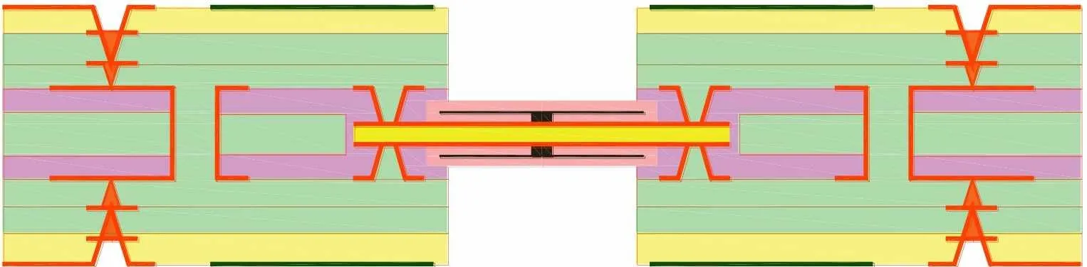
| Maximum flex layers | Up to 10 layers possible | 1–2 layers recommended |
| Copper type | ED or RA acceptable | RA copper required |
| Failure mode | Creep / stress relaxation | Fatigue cracking |
3. The Bend Radius Rule: IPC-2223 Explained
IPC-2223, the sectional design standard for flexible and rigid-flex printed boards, defines the minimum bend radius based on three factors: total thickness of the flex stack-up, number of conductor layers, and type of bend (static or dynamic); . The relationship is straightforward: thicker flex sections require larger bend radiidynamic bends require much larger radii than static bends.
3.1 Static Bend Radius Requirements
For static (bend-to-install) applications, IPC-2223 specifies:
• 1 layer: 6× total flex thickness
• 2 layers: 10–12× total flex thickness
• 3+ layers: 20–24× total flex thickness
Some industry sources quote 3× to 6× for static bends, but conservative engineering practice uses 10× for single/double layer and 20× for multilayer static designs.
3.2 Dynamic Bend Radius Requirements
For dynamic (continuous flex) applications, the requirement is dramatically larger:
• 1 layer: 100× total flex thickness
• 2 layers: 100–150× total flex thickness
• 3+ layers:Not recommended
A typical 0.15mm single-layer flex requires a static radius of 0.9–1.5mm (6–10×) but a dynamic radius of 15mm (100×) — a 10- to 16-fold increase.
3.3 Why the 100× Rule?
The 100× rule is not arbitrary. Bending strain on the outer copper layer is approximately ε ≈ (t_cu + offset) / (2R), where R is the bend radius. For a fixed copper thickness, strain is inversely proportional to bend radius. A 100× radius reduces the strain by a factor of 10 compared to a 10× radius.
Fatigue life follows a power law (Coffin-Manson relationship) — a small reduction in strain produces an exponential increase in cycle life. The 100× rule is the industry's empirically validated threshold for achieving 100,000+ cycles.
The physical origin of the 100× requirement: For a typical 12.5μm polyimide base with 12μm electrolytic copper structure, the neutral plane shifts to approximately one-third of the substrate thickness. The outer copper layer must accommodate tensile strain during each bend cycle. At a 6× radius (static minimum), the strain on the outer copper approaches 1.0–1.2% — close to the fracture strain threshold of electrodeposited copper. At a 100× radius, the strain drops below 0.1%, enabling fatigue life to extend from thousands to millions of cycles.
Dynamic bending stress can only be reliably ensured with single- and double-layer flexible PCBs. Multi-layer flex constructions simply cannot achieve the required bend radius in most product form factors.
4. Layer Count and Material Constraints
4.1 Layer Count: The Fundamental Limitation
For dynamic bending, the number of flex layers must be strictly limited — 1–2 layers maximum. Each additional layer increases total thickness, which increases bending strain proportionally. A 4-layer flex that is 0.5mm thick would require a dynamic bend radius of 50mm (100×) — impractical for most product enclosures.
Static flexes, by contrast, can accommodate up to 10 layers because they only bend once.
4.2 Copper Type: RA vs. ED — A 1,000× Difference
The copper type is a non-negotiable differentiator between static and dynamic designs.
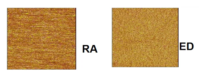
RA (rolled annealed) copper is produced by mechanically rolling a copper ingot and then heat-treating it (annealing) to increase ductility. The result is a fine-grained, equiaxed grain structure with excellent mechanical flexibility. RA copper's elongation can reach 20–30%, and its fatigue endurance is superior across all test conditions.
ED (electrodeposited) copper is formed by electroplating copper onto a rotating drum. The grain structure is vertical (columnar) and anisotropic, making the foil stiffer and more brittle. ED copper typically achieves only 10–15% elongation.
The performance gap is enormous:
• ED copper: Typically withstands fewer than 1,000 flex cycles at a 5mm bend radius before cracking
• RA copper: Can survive over 1,000,000 flex cycles at the same 5mm bend radius
This represents a 1,000× improvement in fatigue life. For dynamic applications targeting 50,000+ cycles, RA copper with documented bend testing is mandatory. ED copper is acceptable only for static bends.
Copper foil comparison for rigid-flex applications
| Property | ED Copper | RA Copper |
|---|---|---|
| Grain structure | Columnar, anisotropic | Fine-grained, equiaxed |
| Elongation | 10–15% | 20–30% |
| Flex cycles (@5mm radius) | <1,000 | >1,000,000 |
| Suitability | Static only | Static and dynamic |
| Cost | Lower | Higher |
The longer life of RA copper is attributed to its extremely cubic recrystallization texture — grain orientation that optimally distributes bending stress. This microstructural advantage is why RA copper demonstrates 2–3× longer fatigue life than ED copper in high-vibration and dynamic conditions.
5. Design Guidelines for Maximum Flex Life
5.1 Bend Radius: Always Add Margin
IPC-2223 minimums are minimums, not targets. Add a 20% safety margin beyond IPC minimums. For a 0.2mm dynamic flex, design for 24mm (120×) rather than 20mm.
5.2 Trace Routing: Perpendicular to Bend Axis
Route traces perpendicular to the bend axis. Traces parallel to the bend axis experience full tensile strain and crack rapidly. If the bend is along the Y-axis, route traces along the X-axis through the bend zone. Routing at 90° to the bend axis increases failure risk by 300%.
5.3 Neutral Axis Placement
The neutral axis is where bending strain is zero. Place copper traces at or near this plane.. Use a single conductor layer in the bend zone whenever possible; for two-layer designs, balance the stack-up symmetrically
5.4 Uniform Bend Zone
The bend zone must be completely uniform — no changes in trace width, no direction changes, no vias, no components, no coverlay openings, no variation in copper distribution. Any variation creates a stress concentration point.
Additional rules:
• No plated through holes within the bend area (minimum 20 mils / 0.5mm clearance)
• Avoid 90° bends — use gradual curves
• Use cross-hatched ground planes (≈60% copper) in the flex zone
• Use tear guards to reinforce the flex material along the inside bend radius
5.5 Coverlay Considerations
The coverlay — typically polyimide film with adhesive layer, total thickness 25–75μm — protects the flex circuit from mechanical wear and environmental exposure. For dynamic applications, coverlay termination at the rigid-flex transition must be carefully controlled. Adhesiveless polyimide constructions are preferred for dynamic flex as they eliminate adhesive creep and delamination risks associated with repeated bending.
5.6 Rigid-Flex Transition Zone
The transition from rigid to flex is a natural stress concentration point. Additional design care:
• Provide sufficient space between the transition point and the bending point to minimize stress on the flex layers
• Use gradual transitions — stepped or tapered structures with minimum 1.2mm step width
• Consider stiffeners (stainless steel or FR-4) to distribute mechanical load in the transition zone
6. Summary: The Order of Magnitude Gap in Practice
The difference between static and dynamic flex life is a design decision made at the start of every rigid-flex project. Dynamic designs require 10–15× larger bend radii, 5–10× fewer layers, and RA copper instead of ED. Ignoring these rules leads to premature failure — often in 10,000 cycles or fewer, instead of the required 100,000+.
Practical takeaways:
• Know your application: if it bends more than 100 times, it is dynamic
• Dynamic bend radius = 100× total flex thickness (minimum), plus 20% margin
• Limit flex layers to 1–2 for dynamic applications
• Specify RA copper — ED copper will fail within 1,000 cycles
• Route traces perpendicular to the bend axis
• Place traces on the neutral axis
• Keep the bend zone uniform — no vias, no components, no 90° angles
A well-designed rigid-flex with correct bend radius, RA copper, and neutral-axis trace placement can survive hundreds of thousands of cycles. The same board designed with static rules — 10× radius, ED copper, multiple layers — may fail within 10,000 cycles. The difference is an order of magnitude, and it starts with the bend radius.
7. Frequently Asked Questions:
Q1: What is the difference between static and dynamic bending in rigid-flex PCBs?
A: Static bending (bend-to-install) occurs once during assembly and stays fixed — lifetime fewer than 100 cycles. Dynamic bending occurs repeatedly during normal operation — lifetime more than 100,000 cycles. The design requirements differ by an order of magnitude.
Q2: What bend radius does IPC-2223 require for static vs. dynamic flex?
A: IPC-2223 specifies 6–20× total thickness for static bends and 100–150× for dynamic bends. Dynamic requires 10–15× larger bend radius than static for the same flex thickness.
Q3: Why does dynamic flex require a 100× bend radius?
A: Bending strain is inversely proportional to bend radius. A 100× radius reduces strain by a factor of 10 compared to a 10× radius. Fatigue life follows a power law — small strain reductions produce exponential increases in cycle life.
Q4: How many flex layers can I use for dynamic bending?
A: 1–2 layers maximum for dynamic bending. Three or more layers are not recommended because each layer increases total thickness, which increases bending strain. Static bends can accommodate up to 10 layers.
Q5: Can I use ED copper for dynamic flex applications?
A: No. ED copper has a columnar grain structure and withstands fewer than 1,000 flex cycles before cracking. RA copper is required for dynamic applications targeting 50,000+ cycles. ED copper is acceptable only for static bends.
Q6: How much longer does RA copper last than ED copper in dynamic bending?
A: RA copper can survive over 1,000,000 flex cycles at a 5mm bend radius, while ED copper withstands fewer than 1,000 cycles under the same conditions. — a 1,000× improvement
Q7: What happens if I use a static bend radius for a dynamic application?
A: The flex will fail prematurely — often in 10,000 cycles or fewer instead of the required 100,000+. The copper traces will crack due to fatigue, and the circuit will become intermittent or fail completely.
Q8: How should traces be routed in the bend zone?
A: Traces must be routed perpendicular to the bend axis. Traces parallel to the bend axis experience the full tensile strain and crack rapidly. Routing at 90° to the bend axis increases failure risk by 300%.
Q9: What is the neutral axis and why does it matter?
A: The neutral axis is the plane within the flex where bending strain is zero. Copper traces placed on the neutral axis experience minimal strain and survive the most cycles. Use single-layer flex or balanced symmetric stack-ups to place traces at the neutral axis.
Q10: How do I calculate the minimum bend radius for my rigid-flex design?
A: For static: R_min = 6–20× total flex thickness (depending on layer count). For dynamic: R_min = 100–150× total flex thickness. Always add a 20% safety margin. Consult your PCB manufacturer for material-specific recommendations.
8. About Richfulljoy
Richfulljoy specializes in high-reliability rigid-flex PCB manufacturing for both static and dynamic bending applications — medical implants, wearable devices, aerospace systems, foldable displays, and robotic applications.









