











Rigid-Flex PCB Lamination: Transition Slope Design for Rigid-Flex Thickness Differences
1. Introduction
The rigid-flex PCB is one of the most sophisticated interconnect technologies in modern electronics. By integrating rigid FR-4 sections with flexible polyimide circuits into a single unified structure, it eliminates connectors, reduces weight, and enables three-dimensional packaging that is simply impossible with rigid boards alone. From foldable smartphones and wearable devices to aerospace avionics and medical implants, rigid-flex technology has become indispensable.
Yet for all its advantages, the rigid-flex PCB harbors a fundamental vulnerability: the transition zone — the narrow boundary where the rigid composite material meets the flexible polyimide core. This is where the board's mechanical and electrical integrity is most severely tested. Industry data reveals that over 85% of rigid-flex failures do not originate from faulty electrical schematics but from mechanical anomalies at this critical interface.
At the heart of this vulnerability lies a simple geometric fact: the rigid section is substantially thicker than the flexible section. A typical rigid section might measure 1.6mm, while the flex section may be only 0.2mm thick — an eightfold difference. This thickness disparity, if not managed through careful transition slope design, creates a step structure that concentrates stress, invites delamination, and ultimately compromises the board's reliability.
This article examines the principles, design rules, and manufacturing considerations for transition slope design in rigid-flex PCB lamination, with a focus on managing the thickness difference between rigid and flexible regions.
2. The Thickness Difference Problem
2.1 The Scale of the Disparity
The thickness gap between rigid and flexible sections in a rigid-flex PCB is not a minor detail — it is a fundamental consequence of the materials involved. Rigid sections are built from multiple layers of FR-4 core and prepreg, typically totaling 0.8mm to 1.6mm or more, depending on layer count and copper weights. Flexible sections, by contrast, use thin polyimide cores — often 25μm to 50μm per layer — with thin copper foils (12μm to 18μm).
When the layer count difference between flexible and rigid areas reaches four layers or more, the thickness gap that the prepreg must fill during lamination exceeds 100μm. This is not a trivial gap. It is a void waiting to happen, a stress concentrator waiting to crack.
2.2 The Step Structure Problem
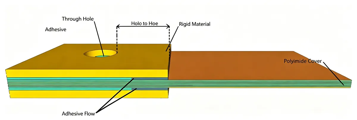
During lamination, the rigid materials are bonded to the flexible core. Because the rigid section is thicker, a step forms at the boundary — an abrupt vertical wall where the thickness changes from the rigid composite to the exposed flex section.
This step structure is mechanically disastrous for several reasons. First, it creates a sharp geometric discontinuity. During bending or thermal cycling, stress concentrates along the transition line, with research indicating that the stress peak in this region can be three to five times the average stress elsewhere in the board. Second, the step makes it difficult for the prepreg to flow and fill the transition area evenly during lamination, leading to voids, resin squeeze-out, or inadequate bonding.. Third, the abrupt thickness change creates an impedance discontinuity that can degrade signal integrity in high-speed applications
2.3 The Failure Modes
The consequences of poor transition design manifest in several distinct failure modes:
Copper trace cracking occurs when the abrupt thickness change concentrates bending strain at a single point, fracturing the copper traces at the transition edge. This is the most common failure mode in dynamic flex applications.
Coverlay delamination happens when the protective polyimide coverlay — which bonds well to polyimide but poorly to FR-4 — lifts at the rigid interface, allowing moisture ingress and corrosion.
Delamination of the entire layer stack occurs when the CTE mismatch between FR-4 and polyimide, combined with poor resin flow at the step, creates voids and weak bonding that separate under thermal stress.
Prepreg bleed — excessive resin extrusion from the prepreg during lamination — can contaminate the flex region, turning a dynamic bend area into a brittle, failure-prone zone.
These failures do not appear immediately. They manifest after assembly, during drop testing, or in the field after hundreds or thousands of flex cycles. They are preventable, but only through deliberate transition slope design.
3. The Role of the Transition Slope
3.1 From Step to Slope
The fundamental principle of transition slope design is simple: replace the abrupt step with a gradual taper.
Instead of a sharp vertical wall where the rigid section ends and the flex section begins, the transition zone should feature a sloped or stepped reduction in thickness. Think of it as a highway off-ramp rather than a cliff edge. The gradual change in thickness distributes the mechanical stress over a larger area, eliminating the single point of concentration that causes failure.
A 45-degree slope angle is commonly recommended for most applications. In one documented case, transitioning from a straight cut to a 45-degree taper increased the flex cycle life by a factor of three. The stress, instead of focusing on one spot, is spread across the entire slope.
3.2 The Mechanical Function
The transition slope serves two mechanical functions. First, it distributes bending stress over a larger area. When the flex section bends, the strain is not concentrated at a single sharp edge but is spread gradually across the sloped region. This reduces the peak strain on the copper traces and the adhesive bonds.
Second, it provides a path for prepreg flow during lamination. A sloped or stepped transition allows the prepreg resin to flow more evenly into the transition zone, filling gaps and creating a stronger bond between the rigid and flexible materials. Without this slope, the prepreg may not reach the deepest parts of the step, leaving voids that weaken the structure.
3.3 The Electrical Function
The transition slope also serves an electrical function. The abrupt thickness change at a step creates an impedance discontinuity because the dielectric thickness and the effective dielectric constant change suddenly. By gradually tapering the thickness over a transition length, the impedance change is smoothed, reducing reflection and signal degradation.
For high-speed digital or RF signals traversing the rigid-flex boundary, this electrical consideration is as important as the mechanical one. The transition length should be sufficient to keep the impedance variation within acceptable limits — typically ±3Ω over the transition zone.
4. Transition Slope Design Parameters
4.1 Slope Angle and Transition Length
The slope angle and transition length are the primary design parameters. The relationship between them is geometric: for a given thickness difference Δt, the transition length L determines the slope angle θ, where tan(θ) = Δt / L.
IPC-2223 specifies that the transition length must be at least five times the flex thickness. For a flex section that is 0.2mm thick, this means a minimum transition length of 1.0mm. However, this is a minimum — for dynamic applications with repeated bending, longer transitions are strongly recommended.
A 45-degree slope, which corresponds to a transition length roughly equal to the thickness difference, is often cited as a practical target. For a thickness difference of 1.4mm (1.6mm rigid minus 0.2mm flex), a 45-degree slope would require a 1.4mm transition length. For more demanding applications, a shallower slope — 30 degrees or less — provides even better stress distribution.
4.2 Stepped vs. Continuous Slope
In practice, the transition is often implemented as a stepped structure rather than a continuous slope. This is because the rigid section is built from multiple layers, and it is easier to step down layer by layer than to create a smooth taper.
A typical stepped transition might involve:
• Rigid section: 6 layers (1.2mm total)
• Step 1: Remove outer layers, leaving 4 layers (0.8mm)
• Step 2: Remove next layers, leaving 2 layers (0.4mm)
• Step 3: Transition to flex section (0.2mm)
Each step should have a minimum width of 1.2mm to 1.5mm, and the corners should be rounded to avoid stress concentration. The step edges should feature fillets with a radius of at least 0.15mm.
The stepped approach is more manufacturable than a continuous slope, but it introduces multiple smaller stress concentrators instead of one large one. With proper step width and rounding, these can be managed effectively.
4.3 The Role of Coverlay
The coverlay — the polyimide film that protects the flex circuit — plays a critical role in the transition zone. It must cover the exposed flex traces without extending too far into the rigid area, where it may not bond properly to FR-4.
The coverlay should terminate before the rigid edge, leaving a small gap. If the coverlay extends into the transition zone, poor adhesion to the FR-4 material can lead to delamination. Conversely, if the coverlay ends too far from the rigid edge, the flex traces near the transition may be unprotected.
A typical design rule is to keep coverlay termination at least 0.5mm to 1.0mm from the rigid-flex boundary, with the exact distance depending on the specific stack-up and flex thickness.
4.4 Trace Routing in the Transition Zone
Traces crossing the transition zone require special attention. The abrupt change in thickness and stiffness creates strain on the copper, and traces that are routed straight through the transition are vulnerable to cracking.
Key design rules for traces in the transition zone:
• Route traces perpendicular to the bend line to minimize stress
• Widen traces by at least 20% in the transition area to improve fatigue resistance
• Avoid placing vias in the transition zone — they are stress concentrators
• Maintain at least 1.0mm clearance between the transition line and any functional feature
• Keep traces evenly distributed across the flex width to avoid localized stiffness
5. Manufacturing Considerations
5.1 Lamination Pressure and Temperature Control
The lamination process for rigid-flex PCBs is more complex than for standard rigid boards. Multiple lamination cycles are typically required. The rigid and flexible materials must be bonded under carefully controlled temperature (170°C to 190°C) and pressure (20 to 25 kg/cm²).
The pressure distribution during lamination is a critical concern. The rigid areas remain stable, but the flexible areas may suffer from wrinkles, stretching, or abnormal resin flow from the prepreg. Controlling the pressure difference between flexible and rigid areas — typically within 0.2 to 0.5 kg/cm² — is essential to balance stress and prevent deformation.
The stepped transition structure makes pressure control more difficult. The prepreg must flow into the step to fill the thickness gap, but excessive pressure can squeeze resin out of the transition zone, contaminating the flex area. Low-flow or no-flow prepregs are typically used to limit resin bleed.
5.2 Spacers and Resin Control
During the final lamination cycle that bonds the rigid and flexible sections together, spacers are inserted into the stack-up to prevent resin from flowing into the flex area. These spacers are later removed through a milling process.
Even with spacers and no-flow prepregs, some resin may still squeeze out beyond the rigid board edge into the transition zone. For flex-to-install applications (one-time bending), this may not be an issue. But for dynamic-flex applications where the board bends repeatedly, hardened resin edges can damage the flexible circuit.
5.3 Defect Tolerance
IPC-6013, the standard for rigid-flex PCBs, defines the transition area as a 3mm-wide zone centered on the rigid board edge axis. Within this zone, certain defects are considered acceptable:
• Lamination voids in the transition area are acceptable
• Protruding rigid dielectric from milling is generally acceptable
• Resin squeeze-out may be acceptable for static applications
However, these defects become unacceptable if any functional features (traces, vias, pads) are placed within the transition zone. The practical guidance is to keep all functional features outside the transition zone.
5.4 Stiffeners and Reinforcement
In some designs, a stiffener — a localized reinforcement — is added across the transition zone to reduce stress. Polyimide stiffeners are used when some flexibility must be retained, while FR-4 stiffeners are used when the specific spot needs to be stiffer.
The stiffener should bridge both the rigid and flex sections, typically extending about 5mm onto each side. This distributes the stress across a larger area and reduces the strain on the transition itself.
6. Summary and Design Checklist
The transition slope is not a cosmetic detail in rigid-flex PCB design. It is the single most important feature for ensuring mechanical reliability at the rigid-flex interface.
Key design rules to remember:
| Parameter | Recommendation |
|---|---|
| Transition length | Minimum 5× flex thickness; longer for dynamic applications |
| Slope angle | 45° target; shallower for demanding applications |
| Step width (stepped design) | Minimum 1.2mm per step |
| Step corner radius | ≥0.15mm |
| Coverlay termination | 0.5–1.0mm from rigid-flex boundary |
| Trace clearance from transition | ≥1.0mm |
| Trace width in transition | Widen by ≥20% |
| Vias in transition zone | Avoid entirely |
| Trace direction | Perpendicular to bend line |
The practical guidance is simple: treat the transition zone with respect. Slope it, don't chop it.. Keep functional features away from the danger zone. And involve your PCB fabricator early — the right transition design depends on their specific lamination process and material capabilities
A well-designed transition slope — whether a continuous taper or a stepped structure — distributes stress, allows proper resin flow, and preserves signal integrity. It is the difference between a rigid-flex PCB that fails in the field and one that survives thousands of flex cycles.
7. Frequently Asked Questions (FAQ)
Q1: Why is the transition zone the highest-risk area in a rigid-flex PCB?
A: The transition zone is where the rigid FR-4 material meets the flexible polyimide core. Multiple stress sources overlap here: different thicknesses, different CTE values, different stiffness, and the presence of adhesive and coverlay boundaries. This combination creates stress concentration that leads to cracking, delamination, and copper fatigue.
Q2: What is the difference between a step and a slope in rigid-flex transition design?
A: A step is an abrupt vertical change in thickness at the rigid-flex boundary. A slope (or stepped taper) is a gradual reduction in thickness over a distance. Slopes distribute stress over a larger area, while steps concentrate stress at a single line.
Q3: What slope angle is recommended for rigid-flex transitions?
A: A 45-degree slope angle works well for most applications.. For demanding dynamic applications with repeated bending, a shallower angle (30 degrees or less) provides better stress distribution. The transition length should be at least five times the flex thickness per IPC-2223
Q4: Can I place vias in the rigid-flex transition zone?
A: No. Vias should not be placed in the transition zone. They act as stress concentrators and can crack during bending or thermal cycling. Maintain at least 1.0mm clearance between any via and the transition line.
Q5: How does coverlay behave in the transition zone?
A: Coverlay bonds well to polyimide but poorly to FR-4. If coverlay extends into the transition zone, poor adhesion can lead to delamination. Coverlay should terminate 0.5–1.0mm before the rigid-flex boundary.
Q6: What are the common failure modes at the rigid-flex transition?
A: The most common failures are copper trace cracking (from bending strain), coverlay delamination (from poor adhesion at the rigid interface), layer delamination (from CTE mismatch and voids), and prepreg bleed (resin contamination of the flex area).
Q7: How should traces be routed through the transition zone?
A: Traces should be routed perpendicular to the bend line, widened by at least 20% in the transition area, and kept evenly distributed across the flex width. No traces should be placed within 1.0mm of the transition line.
Q8: What is the significance of IPC-6013 for rigid-flex transition design?
A: IPC-6013 defines the transition area as a 3mm-wide zone centered on the rigid board edge axis. It specifies acceptable defects (voids, resin squeeze-out) within this zone but requires that functional features be kept outside it.
Q9: When should a stiffener be used at the transition?
A: A stiffener should be used when the flex section needs additional support at the transition, particularly in high-vibration or high-cycle applications. The stiffener should bridge both rigid and flex sections, extending about 5mm onto each side.
Q10: What is the stepped transition approach?
A: The stepped transition approach reduces the rigid section thickness layer by layer, creating multiple smaller steps instead of one large step. Each step should have a minimum width of 1.2mm and rounded corners (R≥0.15mm).









