











Rigid-Flex PCB Post-Bend Testing: Real-Time Impedance Monitoring Methods During Dynamic Bending
1. Introduction: The Hidden Failure
A rigid-flex PCB passes the bend test. It completes 100,000 cycles without visible cracks. It passes electrical inspection afterward. It ships to the customer.
Three months later, it fails in the field. Intermittent signal loss. Random system resets. The customer is frustrated. The failure analysis finds micro-cracks in the flex traces — cracks that were not visible under magnification, cracks that did not affect DC continuity but destroyed high-frequency signal integrity.
This scenario is not hypothetical. It is a documented reality in rigid-flex PCB qualification. Traditional post-bend testing — visual inspection and DC continuity checks — misses a critical class of failures: dynamic impedance shifts that occur during bending and may not persist after the bend is released.
When a flex circuit bends, the copper traces experience strain. This strain changes the geometry of the transmission line — the trace width narrows slightly, the dielectric thickness changes, the copper resistivity increases due to grain boundary deformation. These changes affect characteristic impedance. If the impedance shift exceeds the system tolerance, signal integrity is compromised. But when the bend is released, the copper may spring back, and a post-bend impedance test may show normal values.
The solution is real-time impedance monitoring during dynamic bending. This article examines the methods, standards, and design considerations for detecting dynamic failures that post-test inspection cannot capture.
2. Why Post-Bend Testing Is Not Enough
2.1 The Gap in Traditional Qualification
Traditional rigid-flex PCB qualification relies on post-bend inspection. The test sequence is straightforward:
1. Perform the specified number of bend cycles
2. Remove the board from the test fixture
3. Perform visual inspection (microscope, 10–20× magnification)
4. Perform electrical testing (continuity, insulation resistance, impedance)
This approach has a fundamental limitation: it only detects failures that persist after bending stops.
Dynamic failures — those that occur only during bending — are invisible to post-bend inspection. A trace may crack open during bending and close again when the board is flat. A cracked trace may still pass DC continuity because the crack faces touch. But at high frequencies, the crack creates a reflection that destroys signal integrity.
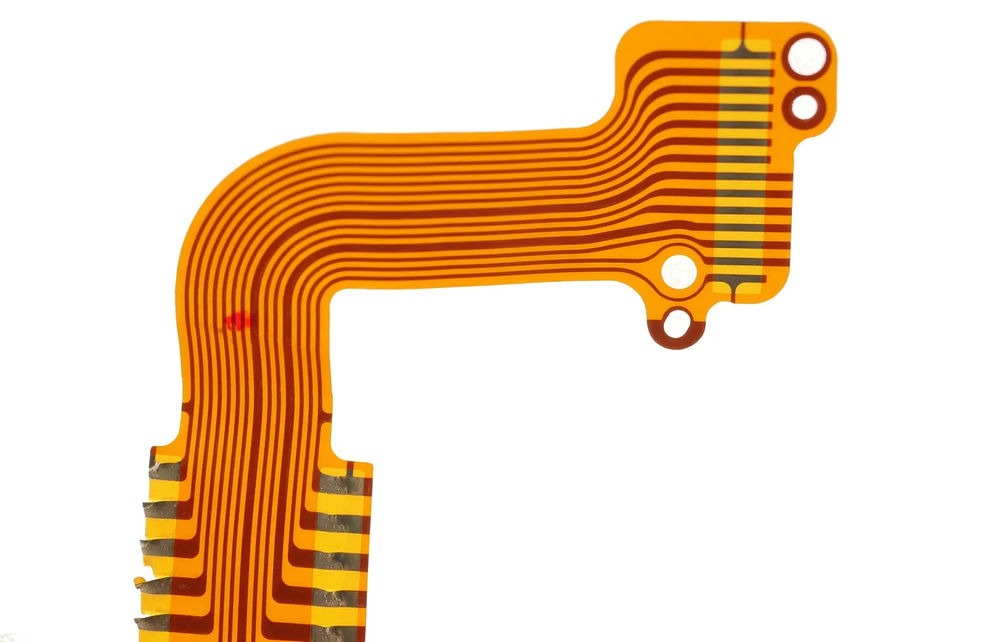
2.2 The Types of Dynamic Failures
Micro-cracks that open and close: The most insidious dynamic failure is the micro-crack that opens during bending and closes when the board is flat. These cracks are often invisible under magnification (crack width <1μm) and may pass DC continuity tests. But at RF frequencies (>1GHz), the crack acts as a series capacitor or a reflection point, degrading return loss and increasing insertion loss.
Impedance drift: Bending stress causes permanent changes in the copper grain structure, increasing resistivity. The trace width may narrow slightly due to plastic deformation. The dielectric thickness may change due to compression or delamination. These changes shift characteristic impedance, sometimes beyond specification. The shift is measurable during bending but may not be detectable afterward.
Intermittent opens: Some cracks open only at specific bend angles. A trace may crack at 90° bend but close at 45°. Post-bend testing at 0° (flat) would show no failure. Real-time monitoring during the bend cycle would detect the intermittent open.
Phase shift: In high-speed differential pairs, bending can create a phase shift between the positive and negative legs of the pair. One trace may experience more strain than the other, creating a skew that degrades signal timing. This skew is only measurable during bending.
2.3 The Cost of Missing Dynamic Failures
The consequences of missing dynamic failures are severe. A 2025 industry study found that 62% of field returns in dynamic rigid-flex applications were attributed to dynamic failure mechanisms that passed traditional post-bend inspection. The most common failure signature was "intermittent signal loss" — exactly the type of failure that real-time monitoring is designed to detect.
The cost of these failures extends beyond warranty claims. They create customer dissatisfaction, damage brand reputation, and can lead to safety risks in automotive and medical applications. In one documented case, a medical device manufacturer recalled 50,000 units after a rigid-flex PCB failure in a drug delivery pump — a recall that cost over $10 million and damaged the company's reputation for reliability.
3. Real-Time Impedance Monitoring Methods
3.1 Time-Domain Reflectometry (TDR) Monitoring
TDR is the most common method for real-time impedance monitoring during dynamic bending.
How it works: A TDR instrument sends a fast rise-time step pulse down the transmission line. When the pulse encounters an impedance change (a crack, a narrowing trace, a dielectric change), a reflection is generated. The instrument measures the time and amplitude of the reflection, calculating the impedance profile along the line.
During dynamic bending: The TDR can be configured to continuously monitor impedance during the bend cycle. Each bend cycle generates a new impedance profile. By comparing profiles across cycles, the test engineer can detect:
• Impedance drift: The average impedance shifting over time
• Transient events: Spikes in impedance that occur at specific bend angles
• Intermittent discontinuities: Reflections that appear and disappear between cycles
Advantages:
• High spatial resolution — can locate the exact position of the failure
• Real-time monitoring — captures dynamic failures as they occur
• Quantitative results — provides numerical impedance values
Limitations:
• Requires access to the transmission line — test probes must be connected during bending
• May affect the bend fixture design — probes and cables must accommodate the bending motion
• Limited to transmission lines that are accessible at both ends
3.2 Vector Network Analyzer (VNA) Monitoring
VNA monitoring measures S-parameters (return loss S11, insertion loss S21) in real time during dynamic bending.
How it works: A VNA measures the reflection and transmission coefficients of the transmission line as a function of frequency. During dynamic bending, the VNA can be configured to sweep continuously, capturing the frequency-domain response at each bend cycle.
During dynamic bending: The VNA monitoring reveals:
• Return loss degradation: Increased reflections at specific frequencies
• Insertion loss increase: Additional loss due to micro-cracks or delamination
• Resonance shifts: Changes in the resonant frequency of the transmission line
Advantages:
• Frequency-domain information — reveals frequency-dependent effects
• Detects subtle changes that TDR might miss
• Standard equipment in most RF labs
Limitations:
• Slower than TDR — sweep time limits the bend speed
• More complex setup — requires full S-parameter calibration
• Requires more expensive test equipment
3.3 Four-Wire (Kelvin) Resistance Monitoring
Four-wire resistance monitoring (also called Kelvin sensing) measures the resistance of the copper traces in real time during bending.
How it works: Two separate connections are made to each end of the trace: one pair carries the test current, the other pair measures the voltage. This eliminates the effects of contact resistance, allowing precise measurement of the trace resistance. A 10% resistance increase is often the first sign of fatigue damage.
During dynamic bending: Continuous monitoring reveals:
• Resistance drift: Gradual increase in trace resistance due to grain boundary damage
• Transient spikes: Resistance increases that occur only at specific bend angles
• Cyclic fluctuations: Resistance changes that follow the bend cycle
Advantages:
• Simple setup — only DC measurements required
• Highly sensitive — can detect damage before it becomes visible
• Inexpensive — standard multimeters with Kelvin capability
Limitations:
• Provides only a single resistance value for the entire trace
• Cannot locate the position of the failure
• Does not provide frequency-domain information
3.4 Comparison Summary
Table 1 — Real-time monitoring methods comparison
| Method | What It Measures | Spatial Resolution | Setup Complexity | Best For |
|---|---|---|---|---|
| TDR | Impedance profile | High (<1mm) | Moderate | Locating failures, impedance drift |
| VNA | S-parameters | Low (frequency-domain) | High | Frequency-dependent effects |
| Four-wire resistance | Total trace resistance | None | Low | Early damage detection |
4. Real-Time Impedance Monitoring in Practice
4.1 Test Setup Considerations
Implementing real-time impedance monitoring requires careful test fixture design.
Probe access: The transmission line must be accessible at both ends during bending. This means the probe connections must be located outside the bend zone, or the bend fixture must accommodate flying leads that move with the board.
Cable management: The cables from the probes to the test equipment must not constrain the bending motion. This typically requires flexible cables with sufficient length and strain relief.
Synchronization: The impedance measurement must be synchronized with the bend cycle to correlate impedance changes with bend angle. This requires a position sensor on the bend fixture that triggers the impedance measurement at specific angles.
4.2 Test Conditions
The test conditions for real-time monitoring should match the actual application conditions as closely as possible.
Dynamic bend test conditions:
| Parameter | Standard Value | Application-Specific Variation |
|---|---|---|
| Bend angle | 90° or 180° reciprocating | Matches product specification |
| Bend speed | 10–30 cycles per minute | Depends on application (faster for high-speed applications) |
| Temperature | Room temperature or elevated | Elevated for automotive/engine bay |
| Total cycles | 100,000–300,000 | Depends on application requirement |
| Stop condition | Failure or target cycle | Failure defined as impedance >% change |
Table 2 — Typical stop conditions for real-time impedance monitoring
| Parameter | Stop Condition | Rationale |
|---|---|---|
| Impedance shift (TDR) | >±10% from initial | Exceeds typical system tolerance (±5–10%) |
| Return loss (VNA) | S11 > -10dB | Unacceptable reflection |
| Resistance increase (four-wire) | >10% increase | Indicates significant copper damage |
| Intermittent open | Any detection | Critical failure — stop immediately |
4.3 Data Analysis and Interpretation
Real-time monitoring generates large volumes of data. A test of 100,000 cycles with one measurement per cycle creates 100,000 impedance profiles. Effective data analysis is essential.
Trend analysis: Plot the impedance at a specific point on the board as a function of cycle count. A gradual increase in impedance over cycles indicates progressive damage — the copper is becoming thinner and more resistive with each bend.
Angle-dependent analysis: Plot the impedance as a function of bend angle. A spike in impedance at a specific angle indicates a crack that opens at that angle. The angle of the spike remains consistent across cycles if the crack location is stable.
Cycle-to-cycle variation: Calculate the standard deviation of impedance across cycles. An increase in cycle-to-cycle variation indicates that the trace is becoming unstable — the early stage of fatigue failure.
4.4 Interpreting the Failure Signature
The following failure signatures indicate specific failure mechanisms:
| Signature | Indicates | Recommended Action |
|---|---|---|
| Gradual impedance drift (>5% over 100K cycles) | Copper fatigue, grain boundary damage | Widen traces or reduce bend radius |
| Spike at specific bend angle | Micro-crack that opens at that angle | Route traces perpendicular to bend axis |
| Intermittent open (spike >50% impedance change) | Complete trace cracking | Immediately redesign — major reliability issue |
| Increasing cycle-to-cycle variation | Incipient failure | Reduce bend radius or use thinner copper |
| Frequency-dependent degradation (VNA) | Delamination or dielectric damage | Use adhesiveless polyimide or improve lamination |
5. Design Guidelines for Reliable Dynamic Bend Performance
Real-time impedance monitoring reveals weaknesses in rigid-flex designs. The following guidelines address the most common failure modes identified through monitoring.
5.1 Impedance Drift Prevention
Use RA copper: Rolled annealed copper has a ductile grain structure that resists the grain boundary deformation that causes impedance drift. ED copper is unsuitable for dynamic applications.
Widen traces: Wider traces distribute stress and reduce strain per unit width. For dynamic applications, use 0.2mm minimum trace width in the flex zone.
Reduce copper thickness: Thinner copper (1/2 oz / 17.5μm or less) experiences lower strain for a given bend radius.
Use arc corners: Arc corners reduce stress concentration and prevent the localized impedance spikes that occur at sharp corners.
5.2 Return Loss Degradation Prevention
Maintain trace alignment: Traces that shift relative to each other during bending create differential impedance mismatch. Route traces parallel to each other and perpendicular to the bend axis.
Avoid vias in the bend zone: Vias create rigid spots that concentrate stress and create impedance discontinuities.
Use ground-reference planes: A solid or hatched ground plane on the opposite side of the flex provides a consistent reference, reducing impedance variations.
5.3 Phase Shift Prevention (Differential Pairs)
Symmetric routing: Route both legs of the differential pair identically through the flex zone.
Match trace lengths: Ensure both legs have the same length to avoid skew.
Controlled dielectric: Use uniform dielectric thickness across the flex zone to maintain constant propagation velocity.
6. Summary: The Case for Real-Time Monitoring
Post-bend inspection is not enough for rigid-flex PCB qualification. Dynamic failures — impedance drift, micro-cracks, intermittent opens — occur during bending and may not be detectable after the bend stops.
The key takeaways:
• Post-bend inspection misses dynamic failures — cracks that open and close, impedance drift, intermittent opens
• 62% of field returns in dynamic rigid-flex applications are attributed to dynamic failure mechanisms
• TDR monitoring provides the best combination of spatial resolution and real-time capability
• Four-wire resistance monitoring is the simplest and least expensive option
• VNA monitoring provides frequency-domain insight for high-frequency applications
• Real-time monitoring reveals failure signatures that guide design improvements
A rigid-flex PCB that passes post-bend inspection may still fail in the field. Real-time impedance monitoring during dynamic bending is the only way to detect the dynamic failures that cause field failures. The investment in real-time monitoring is far less than the cost of a field failure, a product recall, or a damaged reputation.
7. Frequently Asked Questions
Q1: Why is post-bend inspection not sufficient for rigid-flex PCB qualification?
A: Post-bend inspection only detects failures that persist after bending stops. Dynamic failures — micro-cracks that open and close during bending, impedance drift, intermittent opens — may not be visible or electrically detectable when the board is flat.
Q2: What is TDR monitoring and how does it work?
A: TDR (time-domain reflectometry) monitoring sends a fast pulse down the transmission line and measures reflections from impedance changes. During dynamic bending, it continuously monitors the impedance profile, detecting cracks, narrowing traces, and delamination as they occur.
Q3: How does real-time monitoring detect dynamic failures?
A: Real-time monitoring captures impedance changes that occur during bending. A crack that opens at a specific bend angle creates a transient impedance spike that is only measurable during bending. Post-bend testing would miss this entirely.
Q4: What is the most common dynamic failure mode in rigid-flex PCBs?
A: Micro-cracking of copper traces in the flex zone. These cracks may not be visible under magnification and may not affect DC continuity, but they cause impedance changes that degrade high-frequency signal integrity.
Q5: What are the stop conditions for real-time impedance monitoring?
A: Typical stop conditions include: impedance shift >±10% from initial, return loss > -10dB, resistance increase >10%, or detection of any intermittent open.
Q6: What does a spike in impedance at a specific bend angle indicate?
A: It indicates a micro-crack that opens at that bend angle. The spike should be correlated with the bend angle to identify the crack location. Design changes (wider traces, arc corners) may be needed.
Q7: What is the simplest method for real-time monitoring?
A: Four-wire (Kelvin) resistance monitoring is the simplest and least expensive. It measures trace resistance during bending, detecting increases that indicate copper damage. However, it cannot locate the failure.
Q8: How does copper type affect impedance drift under dynamic bending?
A: RA copper has a ductile grain structure that resists grain boundary deformation, reducing impedance drift. ED copper has a brittle columnar structure that is more susceptible to fatigue and impedance drift.
Q9: What does increasing cycle-to-cycle impedance variation indicate?
A: It indicates incipient failure — the trace is becoming unstable and micro-cracks are forming. This is the earliest warning sign of fatigue damage and should trigger design review.
Q10: How should traces be routed to minimize dynamic impedance variation?
A: Traces should be routed perpendicular to the bend axis, with arc corners (not 45° or 90° corners), widened in the flex zone, and kept parallel to each other. Vias should be avoided in the bend zone.
8. About Richfulljoy
Richfulljoy specializes in high-reliability rigid-flex PCB manufacturing with advanced qualification testing capabilities. Our test laboratory is equipped for real-time impedance monitoring during dynamic bending.
- Rigid-Flex PCB Lamination: Transition Slope Design for Rigid-Flex Thickness Differences
- Copper Grain Direction vs, Bending Axis; The First Principle Determining Dynamic Flex Life of Riaid-Flex PCBs
- Rigid-Flex PCB Bend Radius Limits: Dynamic vs Static Flex Life Differs by an Order of Magnitude
- Rigid-Flex Flex Area Routing: How Arc vs. 45° Corners Impact Dynamic Bend Life
- Rigid-Flex PCB Electromagnetic Shielding: Flex Area Shield Layer Design — Critical Considerations Often Overlooked
- Rigid-Flex PCB CAF Risk: CAF Pathways in the Flex Area Are Different from Those in the Rigid Area









