











Rigid-Flex Flex Area Routing: How Arc vs. 45° Corners Impact Dynamic Bend Life
1. Introduction: The Corner That Kills the Circuit
In rigid-flex PCB design, the flex zone is where reliability lives or dies. Engineers obsess over bend radius, copper type, and layer count — and rightly so. But there is a smaller, often overlooked variable that can undo all of those efforts: the shape of the trace corner.
A trace that runs straight through a bend zone experiences uniform stress. A trace that turns — even at a gentle 45° — introduces a stress concentration point. And in dynamic bending applications, that point becomes the nucleation site for fatigue cracks.
Industry data confirms the scale of the problem. IPC-6013 identifies 90° corners as stress risers that increase crack risk by 40% . One wearable device manufacturer found that 90° corners caused 40% of their flexible trace cracks; switching to rounded bends reduced that figure to just 8% . Finite element analysis of a wearable flex PCB showed that rounding trace corners with a 0.1mm radius reduced peak stress by 40%, extending flex life from an estimated 10,000 cycles to over 200,000 cycles .
This article examines the mechanical rationale behind corner geometry in flex zone routing, compares arc corners against 45° corners, and provides practical design rules for maximizing dynamic bend life.
2. The Mechanical Reality of Trace Corners
2.1 Why Corners Concentrate Stress
When a flexible PCB bends, the copper traces on the outer surface of the bend experience tensile strain. This strain is distributed relatively evenly along a straight trace. But at a corner — any corner — the strain distribution changes dramatically.
At a sharp corner, the copper experiences stress concentration: the strain lines crowd together at the inside of the turn, creating a localized region where the stress can be 3–4× higher than in the straight sections of the trace . This is the point where microcracks initiate.
The mechanism is intuitive: a trace corner is a geometric discontinuity. The copper must change direction, and the bending stress — which acts along the length of the trace — now has a component that acts across the width of the trace at the corner. This creates a shear stress component that accelerates fatigue.
2.2 45° Corners: Better Than 90°, But Still a Risk
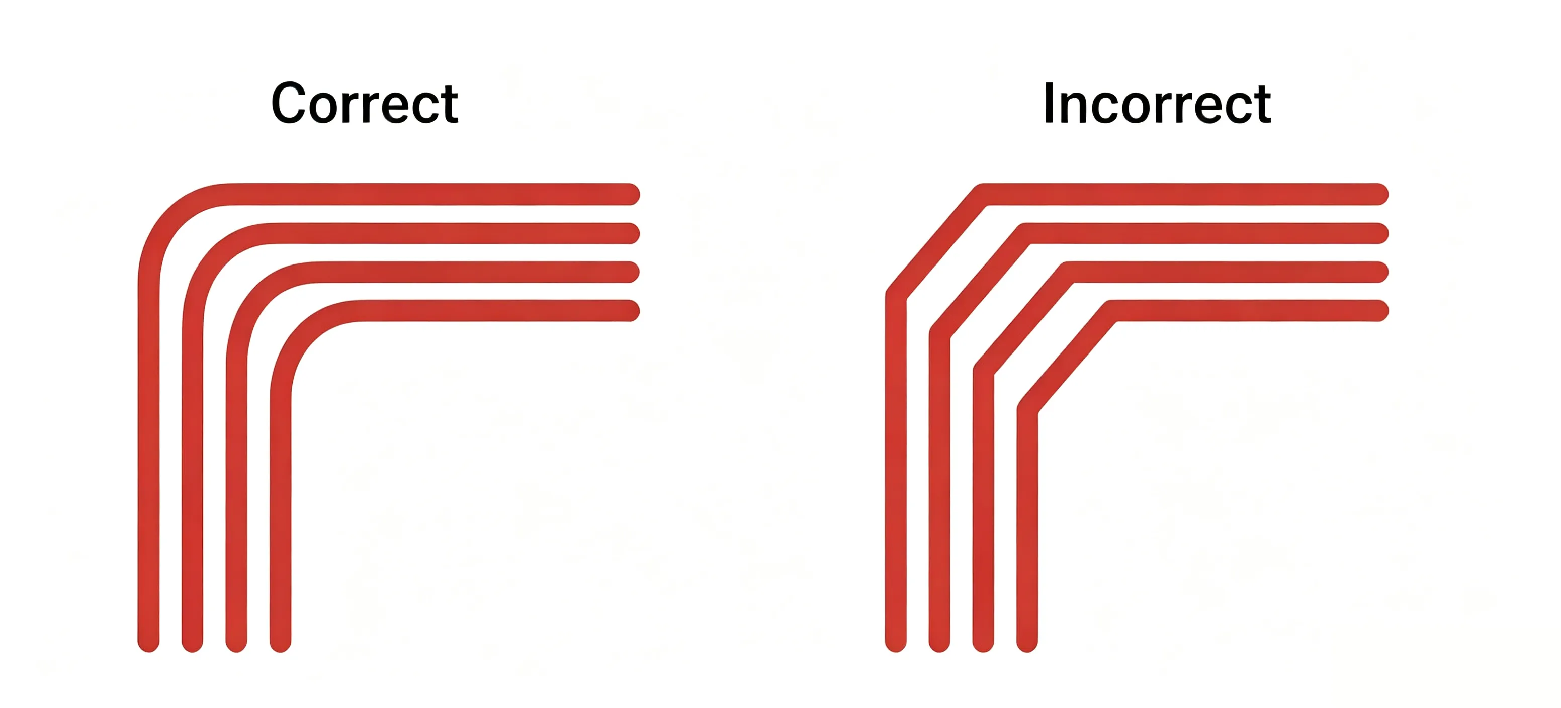
Many designers have learned to avoid 90° corners in flex zones, replacing them with 45° corners. This is an improvement — 90° corners create the sharpest stress concentration . But 45° corners are still stress concentrators.
The 45° corner reduces the severity of the stress concentration compared to 90°, but it does not eliminate it. The copper still undergoes an abrupt change in direction. The stress concentration factor at a 45° corner, while lower than at 90°, remains significantly above 1.0. In dynamic applications with hundreds of thousands of cycles, even a modest stress concentration can lead to fatigue failure.
As one industry observer noted, if you bend outwards with a sharp corner, you risk trace breakage that doesn't happen immediately — it happens after the flex has been in the field for a few months . This delayed failure is the hallmark of fatigue.
2.3 Arc Corners: The Smooth Transition
Arc corners — traces that turn with a smooth, rounded curve — eliminate the abrupt change in direction. The stress is distributed gradually across the curve rather than concentrated at a single point.
The larger the radius of the arc, the lower the stress concentration . A trace that turns with a 0.5mm radius experiences significantly lower peak stress than one that turns with a 0.1mm radius. The ideal is to use the largest arc radius that the design can accommodate.
Smooth, curved traces distribute strain far more evenly than sharp corners, which tend to concentrate stress and eventually crack . This is not a marginal improvement — it is a fundamental mechanical principle that translates directly into cycle life.
3. The Data: What the Numbers Say
The difference between arc and 45° corners is not theoretical. It has been measured, tested, and quantified.
Study 1 — Wearable device flex PCB:
A manufacturer of wearable electronics analyzed the root causes of flex trace cracking in their products. They found that 90° corners caused 40% of all flexible trace cracks. After switching to rounded bends, the failure rate dropped to 8% — a 5× reduction in crack-related failures .
Study 2 — Finite element analysis of a wearable flex PCB:
Using finite element analysis, engineers modeled a flex PCB with trace corners of varying geometries. Rounding trace corners with a radius of just 0.1mm reduced peak stress by 40%. The estimated flex life extended from 10,000 cycles to over 200,000 cycles — a 20× improvement.
Study 3 — Stress measurement in automotive sensor flex designs:
In automotive sensor flex designs, engineers measured stress concentrations 3–4× higher at trace corners within bend zones compared to straight sections . This means that a trace that would survive 100,000 cycles if straight may fail in 25,000–33,000 cycles if it contains an un-optimized corner.
Table 1 — Corner geometry impact on flex life
| Corner Type | Stress Concentration | Relative Flex Life | Failure Rate (Industry Data) |
|---|---|---|---|
| 90° corner | Highest (stress riser) | 1× (baseline) | 40% of all trace cracks |
| 45° corner | Moderate | ~2–3× | Reduced vs. 90°, but still significant |
| Arc corner (0.1mm radius) | 40% reduction vs. sharp | ~20× (from 10K to 200K+ cycles) | ~8% of trace cracks |
The message is clear: arc corners are not a "nice to have" — they are a requirement for any dynamic bending application targeting more than a few thousand cycles.
4. The Physics: Why Arcs Work
4.1 Stress Distribution
The mechanical advantage of arc corners comes down to stress distribution.
At a sharp corner, the bending stress is concentrated at the inside vertex. The copper must accommodate the full strain in a very small volume of material. This leads to localized plastic deformation, work hardening, and eventually, crack initiation.
At an arc corner, the stress is spread across the entire curve. The copper gradually changes direction, and the strain is distributed over a larger volume. The peak stress is significantly lower, and the copper can accommodate more cycles before fatigue sets in.
4.2 Crack Propagation
Once a microcrack initiates at a stress concentration point, it propagates along the path of least resistance. At a sharp corner, that path is short — the crack can quickly traverse the width of the trace, leading to complete fracture.
At an arc corner, the crack must navigate a longer, more tortuous path. The smooth geometry does not provide a direct line for crack propagation. This extends the time between crack initiation and complete failure.
4.3 The Role of Copper Grain Structure
The benefit of arc corners is amplified when combined with the right copper type. Rolled annealed (RA) copper — with its layered, ductile grain structure — can accommodate the gradual stress distribution of an arc corner far better than electrodeposited (ED) copper .
RA copper is mandatory for dynamic flex applications . It offers 50% higher flexibility than ED copper and supports 100,000+ bend cycles . When combined with arc corners, RA copper delivers the maximum possible fatigue life.
5. Design Guidelines for Flex Zone Routing
5.1 Corner Geometry Rules
Rule 1: Use arc corners exclusively in the flex zone.
Do not use 45° corners in the bend area. Do not use 90° corners. Every trace turn in the flex zone should be a smooth arc .
Rule 2: Maximize the arc radius.
Use the largest arc radius that the design can accommodate. A minimum of 0.5mm is recommended for most applications; 0.8mm is preferred for high-current paths . The larger the radius, the lower the stress concentration.
Rule 3: Maintain consistent spacing through the bend.
Do not route traces tightly grouped to one edge of a flex. Use uniform spacing through the bend area . Uneven spacing creates localized stress concentrations.
Rule 4: Use teardrops at pad-to-trace transitions.
The transition from a trace to a pad is another stress concentration point. Add teardrops at trace-pad junctions — this can reduce stress by up to 40% .
5.2 Trace Width and Routing Direction
Rule 5: Widen traces in the flex zone.
Flexible zone traces should be wider than rigid zone traces — 0.2mm or more, compared to 0.1mm in rigid zones . Wider traces distribute stress better and resist cracking.
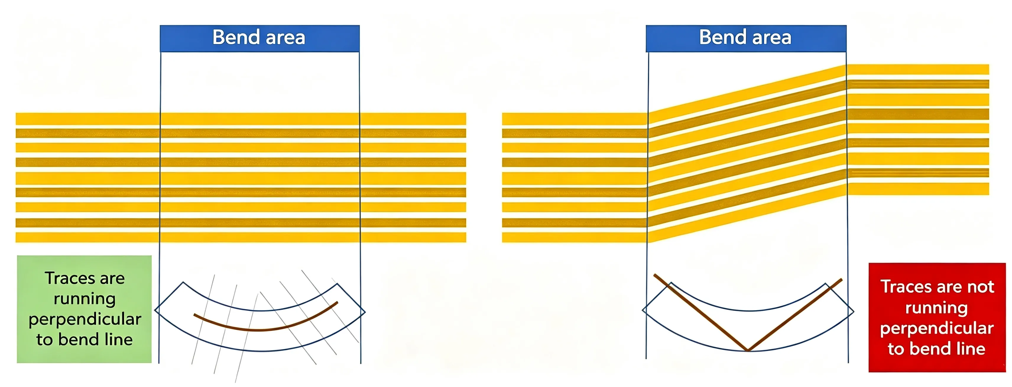
Rule 6: Route traces perpendicular to the bend axis.
Traces that run perpendicular to the bend axis experience minimal strain . Traces that run parallel to the bend axis experience the full tensile strain. Routing at 90° to the bend axis increases failure risk by 300% .
Rule 7: Stagger traces on adjacent layers.
For multi-layer flex designs, stagger traces on adjacent layers by 0.5× the trace width. This reduces stress concentration and lowers failure rates by 30% in dynamic flexing .
5.3 What to Avoid in the Flex Zone
Avoid vias in the flex zone. Vias create rigid spots that concentrate stress . Place vias at least 1mm from bend lines, and 2mm for dynamic bending applications.
Avoid components in the flex zone. Components add stiffness and create stress concentration points . Place all SMDs and connectors in rigid sections.
Avoid abrupt changes in trace width. Sudden changes in trace width create stress concentration points . Use smooth transitions.
6. Summary: The Corner That Determines Life
The shape of a trace corner in the flex zone is not a cosmetic choice. It is a mechanical decision that directly determines the dynamic bend life of the rigid-flex PCB.
The key takeaways:
• 45° corners are better than 90°, but they still create stress concentration. Arc corners are superior.
• Arc corners reduce peak stress by up to 40% compared to sharp corners .
• Arc corners can extend flex life from 10,000 cycles to over 200,000 cycles .
• The largest possible arc radius should be used in the flex zone.
• RA copper is required for dynamic applications — ED copper will fail.
• Teardrops at pad-to-trace transitions reduce stress by up to 40% .
• No vias, no components, no abrupt changes in the flex zone.
A rigid-flex PCB with arc corners, RA copper, correct bend radius, and neutral-axis trace placement can survive hundreds of thousands of cycles. The same design with 45° corners may fail in tens of thousands. The difference is the corner.
7. Frequently Asked Questions
Q1: Why are 45° corners a problem in flex zone routing?
A: 45° corners create stress concentration points. While better than 90° corners, they still cause an abrupt change in direction that concentrates bending stress. This leads to fatigue crack initiation and propagation over repeated bend cycles.
Q2: How much better are arc corners than 45° corners for flex life?
A: Finite element analysis shows that rounding trace corners with a 0.1mm radius reduces peak stress by 40% and can extend flex life from 10,000 cycles to over 200,000 cycles — a 20× improvement .
Q3: What arc radius should I use in the flex zone?
A: Use the largest radius that the design can accommodate. A minimum of 0.5mm is recommended; 0.8mm is preferred for high-current paths . Larger radii distribute stress more evenly.
Q4: Can I use 45° corners if my application is static (bend-to-install)?
A: Yes. Static applications with fewer than 100 bend cycles are more forgiving. 45° corners are acceptable for static flex. However, arc corners are still recommended for maximum reliability.
Q5: What is the most common cause of flex trace cracking?
A: Stress concentration at trace corners is one of the most common causes. Industry data shows that 90° corners cause 40% of flexible trace cracks; switching to rounded bends reduces this to 8% .
Q6: Does copper type affect how corners perform?
A: Yes. RA copper has a ductile, layered grain structure that accommodates stress better than ED copper. RA copper is mandatory for dynamic flex applications and works synergistically with arc corners .
Q7: Should I use teardrops at trace-pad junctions in the flex zone?
A: Yes. Teardrops reduce stress at the transition from trace to pad by up to 40% . This is especially important in the flex zone where stress concentration is already a concern.
Q8: Can I place vias in the flex zone if they are small?
A: No. Vias create rigid spots that concentrate stress, regardless of size. Place vias at least 1mm from bend lines, and 2mm for dynamic bending applications .
Q9: How should traces be oriented relative to the bend axis?
A: Traces should be routed perpendicular to the bend axis. Routing at 90° to the bend axis increases failure risk by 300% . Traces parallel to the bend axis experience the full tensile strain.
Q10: Does trace width affect corner performance?
A: Yes. Wider traces distribute stress better. Flexible zone traces should be 0.2mm or more, compared to 0.1mm in rigid zones . Wider traces resist cracking at corners.
8. About Richfulljoy
Richfulljoy specializes in high-reliability rigid-flex PCB manufacturing for dynamic bending applications — foldable displays, wearable devices, medical devices, automotive sensors, and aerospace systems.









