











Rigid-Flex PCB CAF Risk: CAF Pathways in the Flex Area Are Different from Those in the Rigid Area
1. The Same Failure Mode, Different Paths
Conductive anodic filament (CAF) formation is one of the most insidious failure modes in printed circuit boards. It occurs subsurface, along the glass fiber-resin interface, and can take hundreds or thousands of hours to manifest — long after the board has passed electrical test and been shipped into the field. When a CAF filament bridges two oppositely biased conductors, the result is a low-resistance short that can cause catastrophic system failure.
In rigid PCBs, CAF behavior is relatively well understood. Filaments grow along the epoxy-glass interface, typically between plated through-holes, following the woven glass weave pattern. Design rules, material selections, and test methods (IPC-TM-650 2.6.25) have been developed around this understanding.
However, in rigid-flex PCBs, the flex area presents a fundamentally different environment for CAF formation. The materials are different — polyimide rather than FR-4 epoxy. The glass reinforcement, if present, has a different weave and resin content. The conductor configurations are different — traces on the same layer rather than hole-to-hole. And the mechanical stresses from bending create additional pathways for moisture ingress and interface degradation.
This article examines why CAF pathways in the flex area of a rigid-flex PCB differ from those in the rigid area, what this means for reliability, and how designers can mitigate CAF risk through material selection, design rules, and manufacturing controls.
2. CAF Fundamentals: The Two-Step Mechanism
Before examining the differences between rigid and flex areas, it is essential to understand the fundamental mechanism of CAF formation.
CAF formation occurs in two distinct steps.
Step 1 — Physical degradation of the resin-glass interface: When moisture is absorbed into the PCB substrate, it creates an aqueous medium along the interface between the resin and the glass fibers. This degradation can be caused by hydrolysis of the organosilane bonds that couple the glass to the resin, or by mechanical stresses from thermal cycling that exploit coefficient of thermal expansion (CTE) mismatches. If there is voiding in the PCB material — such as low resin content in tight weaves — CAF growth occurs even more readily.
Step 2 — Electrochemical reaction: Once a continuous moisture path is established between two conductors at different potentials, an electrochemical cell is formed. Copper dissolves from the anode (Cu → Cu²⁺ + 2e⁻), migrates through the aqueous path along the degraded interface, and deposits at the cathode. Over time, this filament of copper-containing salts bridges the conductors, creating a low-resistance short.
The critical insight is that CAF requires three ingredients: (1) a voltage gradient between conductors, (2) moisture to create an electrolytic path, and (3) a degraded pathway along which ions can migrate — typically the glass fiber-resin interface.
In rigid PCBs, the glass fiber-resin interface is the dominant pathway. In flex areas, the situation is more complex.
3. CAF in Rigid Areas: The Classical Pathway
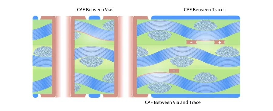
In the rigid sections of a rigid-flex PCB — typically constructed from FR-4 or similar epoxy-glass laminates — CAF follows the well-characterized pathway along the glass fiber-epoxy interface.
The dominant pathway: The glass fibers in FR-4 are woven in a 0°/90° pattern. The interface between the epoxy resin and the glass fiber bundles is the weakest point in the dielectric structure. Moisture preferentially accumulates at this interface, and the organosilane coupling agents that bond the glass to the resin are susceptible to hydrolysis. Once degraded, this interface provides a continuous pathway for copper ion migration.
The conductor configurations: In rigid PCBs, CAF most commonly occurs between plated through-holes (hole-to-hole), followed by hole-to-trace and trace-to-trace configurations. The susceptibility ranking is hole-to-hole > hole-to-trace > trace-to-trace, due to the direct contact of the plated through-hole barrel with the glass fibers.
The failure signature: CAF in rigid areas typically manifests as a distinct through-type pathway — a filament that grows from one conductor to another, following the glass weave pattern. The filament is subsurface and can only be identified through cross-sectioning or specialized failure analysis techniques.
The test method: IPC-TM-650 Method 2.6.25 is the industry standard for evaluating CAF resistance in rigid PCBs. Test coupons with specific conductor spacings and configurations are subjected to elevated temperature, humidity, and bias voltage for 1,000 hours or more.
4. CAF in Flex Areas: A Different Environment
The flex area of a rigid-flex PCB presents a fundamentally different environment for CAF formation. The materials, structure, and failure mechanisms are distinct from those in rigid sections.
4.1 Material Differences: Polyimide vs. Epoxy
The most significant difference is the base material. Rigid sections use epoxy-glass (FR-4) laminates. Flex areas use polyimide (PI) as the dielectric substrate. Polyimide is chosen for its flexibility, thermal stability, and mechanical durability — but its CAF behavior differs from epoxy.
Polyimide has lower moisture absorption than epoxy (typically 0.3–0.5% vs. 0.6–1.2% for FR-4), which might suggest lower CAF risk. However, the interface between polyimide and any glass reinforcement — if present — is different from the epoxy-glass interface. Polyimide does not bond to glass as strongly as epoxy does, and the absence of organosilane coupling agents in some constructions can create pathways for moisture ingress.
Furthermore, many flex materials are adhesiveless — the copper is bonded directly to the polyimide without an adhesive layer. While this improves flexibility and thermal performance, it creates a different set of interfaces where moisture can accumulate.
4.2 Glass Reinforcement: Often Absent or Different
Rigid PCBs rely on woven glass reinforcement for mechanical strength and dimensional stability. This glass weave provides the primary pathway for CAF growth.
Flex areas, by contrast, may have no glass reinforcement at all. Many flexible circuits use unreinforced polyimide film. Without glass fibers, the classical epoxy-glass interface pathway for CAF does not exist.
However, some flex constructions do include glass reinforcement — particularly in stiffened flex areas or in certain high-reliability applications. When glass is present in a flex area, the weave pattern is typically different from the coarse 0°/90° weave of FR-4. Finer weaves or different glass styles create different pathways and different CAF susceptibility.
4.3 Conductor Configurations: Trace-to-Trace Dominance
In rigid PCBs, CAF most commonly occurs between plated through-holes. In flex areas, plated through-holes are typically avoided in the bend zone because they create stress concentration points that lead to cracking.
Without plated through-holes, the primary CAF pathway in flex areas is trace-to-trace on the same layer. Copper ions migrate laterally across the dielectric between adjacent traces, rather than vertically between layers or between holes.
This difference is significant. Trace-to-trace CAF in flex areas is driven by the spacing between conductors on the same layer — a parameter that is often tighter in dense flex designs than in rigid sections. As conductor spacing decreases, the electric field gradient increases, accelerating CAF formation.
Table 1 — CAF pathway comparison: Rigid area vs. Flex area
| Parameter | Rigid Area (FR-4) | Flex Area (Polyimide) |
|---|---|---|
| Base dielectric | Epoxy-glass | Polyimide (unreinforced or glass-reinforced) |
| Primary CAF pathway | Glass fiber-epoxy interface | Polyimide surface or glass-PI interface |
| Dominant conductor configuration | Hole-to-hole | Trace-to-trace |
| Failure morphology | Through-type pathway | Dendritic growth |
| Primary moisture ingress path | Along glass fibers | Through coverlay edges or defects |
| Mechanical stress contribution | Thermal cycling (CTE mismatch) | Bending stress + thermal cycling |
4.4 Failure Morphology: Dendritic vs. Through-Type
The morphology of CAF failures in flex areas differs from that in rigid areas.
In rigid PCBs, CAF appears as a through-type pathway — a filament that grows along the glass fiber-resin interface, following the weave pattern. The filament is typically straight or follows the glass bundle direction.
In flex areas, CAF manifests as dendritic growth — irregular, branching filaments that migrate haphazardly from cathode to anode. The absence of a regular glass weave pattern means the ions do not have a pre-defined pathway to follow. Instead, they grow along whatever paths are available — surface defects, coverlay delamination, or micro-cracks created by bending stress.
This dendritic morphology makes CAF in flex areas harder to predict and harder to detect. Dendrites can form in unpredictable locations and follow unpredictable paths.
4.5 The Role of Mechanical Stress
The flex area is subject to mechanical bending stress — a factor that does not exist in rigid sections. Bending creates micro-cracks in the copper, the dielectric, and the interfaces between them. These micro-cracks provide additional pathways for moisture ingress and ion migration.
When a flex circuit bends, the copper traces on the outer surface of the bend are placed in tension. This tensile stress can create micro-cracks in the copper that extend into the underlying dielectric. Moisture can penetrate these cracks, creating electrolytic pathways that accelerate CAF formation.
Furthermore, the coverlay — the polyimide film that protects the flex circuit — is another interface where moisture can accumulate. If the coverlay delaminates from the copper or the dielectric, it creates a pathway for moisture and ion migration. Coverlay adhesion is critical for CAF resistance in flex areas.
Table 2 — CAF risk factors: Rigid area vs. Flex area
| Risk Factor | Rigid Area | Flex Area |
|---|---|---|
| Moisture absorption | Moderate (FR-4: 0.6–1.2%) | Lower (PI: 0.3–0.5%) |
| Primary pathway availability | High (glass weave everywhere) | Variable (unreinforced or different weave) |
| Mechanical stress contribution | Low (thermal only) | High (bending + thermal) |
| Coverlay-related risk | None | Significant (coverlay edges and adhesion) |
| Conductor spacing | Typically >0.2mm | Often tighter (<0.15mm) |
5. The Rigid-Flex Transition Zone: A Unique CAF Risk
The transition zone — where the rigid section meets the flex section — deserves special attention. This is where the material, structure, and stress environment all change simultaneously.
Material discontinuity: The transition zone is where epoxy-glass (rigid) meets polyimide (flex). The interface between these two material systems can create pathways for moisture ingress. If the coverlay does not overlap the rigid section adequately, or if the rigid solder mask does not seal against the flex coverlay, moisture can penetrate along the material boundary.
Mechanical stress concentration: The transition zone concentrates mechanical and thermal stress. Abrupt changes in layer count, sudden termination of solid copper planes, and the transition from rigid to flexible construction all create stress concentration points. These stress concentrations can create micro-cracks that provide CAF pathways.
Plated through-hole proximity: In many rigid-flex designs, plated through-holes are placed near the transition zone. These holes provide potential CAF pathways — particularly if they are close to the flex area where moisture ingress is more likely.
The transition zone requires additional design attention for CAF mitigation, including adequate coverlay overlap, gradual layer transitions, and maintaining sufficient distance between plated through-holes and the flex area.
6. Design Guidelines for CAF-Resistant Rigid-Flex PCBs
Given the different CAF pathways in rigid and flex areas, a unified design approach is insufficient. The following guidelines address the unique CAF risks of each region.
6.1 Material Selection
- For rigid sections: Use CAF-resistant laminates with low ion content, high glass transition temperature (Tg >170°C), and tight glass weave (e.g., 106 or 2116 style). Materials such as Isola I-Tera MT40 or Panasonic Megtron 6 offer improved CAF resistance.
- For flex sections: Use high-quality polyimide with verified coverlay adhesion. If glass reinforcement is required, specify fine-weave glass with high resin content to minimize voiding.
- For adhesiveless constructions: Verify that the copper-polyimide interface has adequate adhesion to prevent delamination and moisture ingress.
6.2 Conductor Spacing
- In rigid areas: Follow IPC-2221 spacing guidelines with additional margin for CAF. For 5V designs, maintain minimum spacing of 0.2mm.
- In flex areas: Maintain larger spacing than in rigid areas — minimum 0.25mm for 5V designs. The absence of a glass weave pathway does not eliminate CAF risk; dendritic growth can occur across tighter spacings.
- At the transition zone: Maintain at least 0.3mm spacing between conductors and the rigid-flex boundary.
6.3 Coverlay Design
- Extend the coverlay at least 0.5–1.0mm beyond the rigid-flex boundary to seal the transition.
- Specify coverlay adhesion testing to verify bond strength.
- Avoid coverlay openings in the flex area unless absolutely necessary — each opening is a potential moisture ingress point.
- Use adhesiveless coverlay constructions where possible to eliminate the adhesive interface as a potential CAF pathway.
6.4 Plated Through-Hole Placement
- Avoid plated through-holes in the flex area entirely.
- Maintain a minimum clearance of 1.0mm (40 mils) between plated through-holes and the rigid-flex transition zone.
- For rigid sections near the transition, use tented, plugged, or capped vias to reduce moisture ingress.
6.5 Manufacturing Controls
- Ionic cleanliness: Ensure the board meets ionic cleanliness requirements (IPC-TM-650 2.3.25) — residual ions accelerate CAF formation.
- Desmear process: For flex areas with glass reinforcement, ensure the desmear process does not aggressively attack the glass-resin interface.
- Lamination: Control lamination temperature and pressure to ensure complete resin flow and void-free interfaces.
- Coverlay lamination: Verify coverlay lamination parameters to ensure full adhesion without creating stress in the flex area.
6.6 Testing and Qualification
- For rigid sections, use IPC-TM-650 2.6.25 CAF testing with standard coupons.
- For flex areas, consider flexible substrate CAF testing using simulated test vehicles that replicate the flex material and construction. Traditional rigid PCB CAF coupons may not accurately reflect flex area performance.
- For critical applications, perform combined environmental testing — thermal cycling plus humidity plus bias — to simulate the combined mechanical and environmental stresses of the flex area.
7. Summary: Know the Difference
CAF is a serious reliability threat in rigid-flex PCBs, but the pathways and risks in the flex area are fundamentally different from those in the rigid area.
The key takeaways:
- Rigid areas are susceptible to classical CAF along the glass fiber-epoxy interface, primarily between plated through-holes.
- Flex areas are susceptible to different CAF mechanisms — dendritic growth along polyimide surfaces, coverlay interfaces, and micro-cracks from bending stress.
- The transition zone combines the risks of both regions and requires additional design attention.
- Material selection matters — polyimide has different CAF behavior than FR-4 epoxy.
- Conductor spacing in flex areas should be more conservative than in rigid areas.
- Coverlay design and adhesion are critical for CAF resistance in flex areas.
- Test methods developed for rigid PCBs may not adequately capture flex area CAF risk.
A rigid-flex PCB designed with a unified CAF mitigation strategy — one that does not distinguish between rigid and flex regions — will have gaps in its reliability. The pathways are different. The risks are different. The solutions must be different too.
8. Frequently Asked Questions (FAQ)
Q1: What is CAF and why is it a concern for rigid-flex PCBs?
A: CAF (conductive anodic filament) is an electrochemical failure mode where copper ions migrate along dielectric interfaces under voltage, forming a conductive filament that can short-circuit adjacent conductors. In rigid-flex PCBs, both the rigid and flex areas are susceptible, but the pathways and mechanisms differ.
Q2: How does CAF in the flex area differ from CAF in the rigid area?
A: In rigid areas, CAF grows along the glass fiber-epoxy interface, primarily between plated through-holes. In flex areas, CAF manifests as dendritic growth along polyimide surfaces, coverlay interfaces, and micro-cracks from bending stress, primarily between traces on the same layer.
Q3: Does polyimide have better CAF resistance than FR-4?
A: Polyimide has lower moisture absorption than FR-4, which can reduce CAF risk. However, polyimide does not bond to glass as strongly as epoxy, and the absence of organosilane coupling agents can create different pathways for moisture ingress. CAF resistance depends on the specific material construction.
Q4: Can CAF occur in unreinforced polyimide flex circuits without glass fibers?
A: Yes. Without glass fibers, the classical epoxy-glass pathway does not exist, but CAF can still occur along polyimide surfaces, coverlay interfaces, or through micro-cracks created by bending stress. Dendritic growth can bridge adjacent traces.
Q5: What is the most common CAF pathway in flex areas?
A: Trace-to-trace on the same layer is the most common configuration. Plated through-holes are typically avoided in flex areas, so hole-to-hole CAF is rare. Dendritic growth across the dielectric between adjacent traces is the primary failure mode.
Q6: How does bending stress affect CAF risk in flex areas?
A: Bending creates micro-cracks in copper and dielectric interfaces. These micro-cracks provide pathways for moisture ingress and ion migration, accelerating CAF formation. Coverlay delamination from bending further increases risk.
Q7: What is the role of coverlay in CAF prevention?
A: Coverlay protects the flex circuit from moisture ingress. If the coverlay delaminates or has defects, moisture can penetrate and create electrolytic pathways. Coverlay adhesion and edge sealing are critical for CAF resistance in flex areas.
Q8: Should I use the same conductor spacing in flex and rigid areas?
A: No. Flex areas typically require more conservative spacing — minimum 0.25mm for 5V designs, compared to 0.2mm in rigid areas. Tighter spacing increases the electric field gradient and accelerates CAF formation.
Q9: Does IPC-TM-650 2.6.25 CAF testing apply to flex areas?
A: IPC-TM-650 2.6.25 was developed primarily for rigid PCBs. While it can provide some insight, it may not accurately reflect flex area CAF behavior. Specialized testing using flexible substrates is recommended for critical applications.
Q10: How can I mitigate CAF risk in the rigid-flex transition zone?
A: Extend the coverlay at least 0.5–1.0mm beyond the transition boundary, maintain 1.0mm clearance between plated through-holes and the transition, use gradual layer transitions, and ensure proper sealing between rigid solder mask and flex coverlay.
9. About Richfulljoy
Richfulljoy specializes in high-reliability rigid-flex PCB manufacturing with comprehensive CAF risk mitigation strategies tailored to both rigid and flex regions. Our engineering team understands that CAF pathways in flex areas differ from those in rigid sections and applies region-specific design rules and manufacturing controls.
Our rigid-flex CAF mitigation capabilities:
- Material selection: CAF-resistant laminates for rigid sections (Isola I-Tera MT40, Panasonic Megtron 6); high-quality polyimide for flex sections
- Design support: Region-specific conductor spacing rules, coverlay design optimization, transition zone protection
- Manufacturing controls: Ionic cleanliness verification, controlled lamination, coverlay adhesion testing
- Testing: IPC-TM-650 2.6.25 CAF testing for rigid sections; flexible substrate CAF evaluation for flex areas
- Documentation: Material traceability, test reports, reliability analysis
- Rigid-Flex PCB Lamination: Transition Slope Design for Rigid-Flex Thickness Differences
- Copper Grain Direction vs, Bending Axis; The First Principle Determining Dynamic Flex Life of Riaid-Flex PCBs
- Rigid-Flex PCB Bend Radius Limits: Dynamic vs Static Flex Life Differs by an Order of Magnitude
- Rigid-Flex Flex Area Routing: How Arc vs. 45° Corners Impact Dynamic Bend Life
- Rigid-Flex PCB Electromagnetic Shielding: Flex Area Shield Layer Design — Critical Considerations Often Overlooked









