











Poor EMC Design Can Derail Performance: Key Insights for SMT PCB Engineers
Electromagnetic Compatibility (EMC) is a critical aspect of designing and assembling PCBs, particularly in SMT (Surface-Mount Technology) PCB assembly. As devices become smaller and faster, maintaining high-performance standards while preventing electromagnetic interference (EMI) is crucial for reliable operation. This article delves into the key points for EMC design in SMT PCB assembly, focusing on essential strategies that help mitigate EMI and ensure PCB reliability.
What is Electromagnetic Compatibility (EMC)?
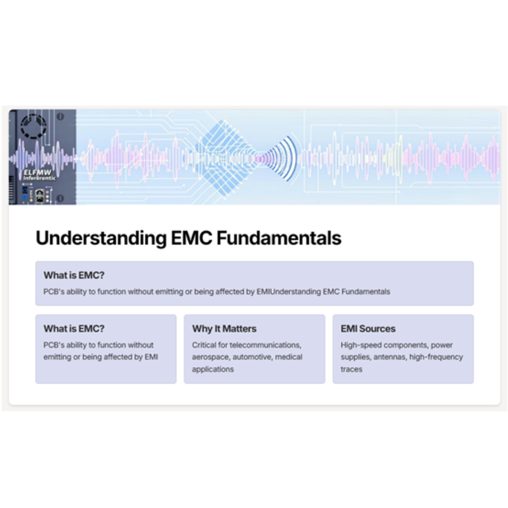
Electromagnetic Compatibility refers to a PCB's ability to function as intended without emitting or being susceptible to electromagnetic interference (EMI) that can disrupt its performance or the operation of nearby devices. Achieving EMC compliance is essential, especially in industries like telecommunications, aerospace, automotive, and medical applications, where signal integrity and system reliability are paramount.
Key Points for EMC Design in SMT PCB Assembly

Understanding the Sources of EMI
The first step in EMC design is identifying the potential sources of EMI. These could be:
- High-speed switching components like microcontrollers or FPGAs.
- Power supply circuits.
- Antennas or other wireless transmission elements.
- High-frequency traces that radiate electromagnetic energy.
Understanding these sources helps in devising strategies to reduce or shield EMI from affecting the PCB or its environment.
Grounding and Power Distribution Networks

Proper grounding is one of the most effective ways to prevent EMI in SMT PCB assembly. A well-designed ground plane provides a low-resistance path for signals to return to the source, preventing noise from propagating across the board. Additionally, carefully designed PDNs reduce power supply noise, which could otherwise lead to system instability.
- Solid Ground Plane: A continuous, uninterrupted ground plane minimizes the path for return currents and shields the circuit from external EMI.
- Power Plane Segmentation: Segmenting power planes can reduce coupling between noisy and sensitive sections of the PCB.
Trace Routing and Layout Techniques
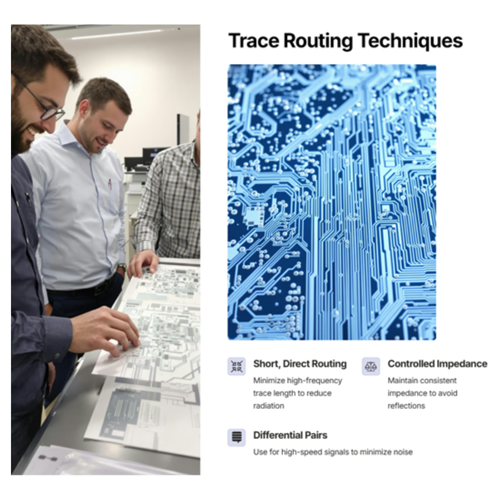
Trace layout is critical in ensuring signal integrity and minimizing EMI. The following layout techniques can be used to mitigate EMI:
- Short, Direct Trace Routing: Minimize the length of high-frequency signal traces to reduce radiation and cross-talk.
- Controlled Impedance: For high-speed signals, ensure that the traces maintain a consistent impedance to avoid reflections and reduce EMI.
- Differential Pairs: Use differential pairs for high-speed signals to minimize noise and improve signal integrity.
Use of Shielding and Enclosures
Shielding is one of the most effective ways to mitigate EMI in sensitive circuits. Shielding can either be applied at the component level or the PCB level. It involves placing a conductive material around the sensitive components or circuit sections to block or absorb unwanted electromagnetic radiation.
- Copper Shields: Copper or other conductive materials can be placed around components or the entire PCB to absorb EMI.
- EMI Gaskets: Sealing enclosures with conductive gaskets also prevents EMI leakage and external interference.
Decoupling Capacitors
Decoupling capacitors play a vital role in stabilizing power supplies and mitigating noise at high frequencies. Placing capacitors close to power pins helps filter out noise and ensure clean power delivery to sensitive components.
- Capacitor Placement: Place decoupling capacitors as close to the power and ground pins of each component as possible to reduce high-frequency noise.
Differential and Common-Mode Filters
EMI can propagate through the power supply and signal lines. To block EMI from entering or leaving the PCB, use differential and common-mode filters. These filters ensure that unwanted electromagnetic signals are suppressed without affecting the operation of the circuit.
- Common-Mode Chokes: These are effective in filtering out common-mode noise and protecting against EMI from power lines.
- Ferrite Beads: Ferrite beads are often used to suppress high-frequency noise on signal and power lines.
PCB Material SelectionPCB
The choice of PCB material plays an essential role in EMC performance. High-frequency PCB materials with low dielectric constants and low-loss tangents are preferable for applications that require high-speed signals.
- Low-Loss Substrates: Use materials such as Rogers or other low-loss laminates for high-frequency applications to reduce signal degradation and EMI.
Testing and Compliance with Standards
Once your PCB is designed, testing is essential to ensure that it meets EMC standards and does not interfere with other devices. Standards like the IEC 61000 series and the FCC Part 15 regulations for electronic devices are commonly used benchmarks for EMC compliance.
- EMC Testing: Conduct both emissions and immunity tests to verify that the PCB operates within permissible limits.
- Validation through Simulation: Use simulation tools to assess the PCB’s electromagnetic behavior and make adjustments before physical testing.
Designing an EMC-compliant PCB in SMT PCB assembly is essential for ensuring the reliability and performance of modern electronic devices. By carefully considering grounding, power distribution, trace routing, shielding, and material selection, engineers can significantly reduce the risk of EMI and improve the overall functionality of their products. Whether you are working with high-speed RF PCBs or low-frequency designs, incorporating these key considerations into your design process will lead to more robust and reliable systems.
By focusing on these crucial design strategies for electromagnetic compatibility, you can avoid performance issues, reduce production costs, and ensure that your product complies with the necessary regulations. Whether you are developing high-frequency or low-frequency PCBs, EMC design should always be a top priority to enhance device performance and user experience.









