Ultimate Guide to Next Generation High Frequency PCB Materials (PTFE / Low Dk Resins)
1. Why Next Gen Materials Define High Frequency PCB Performance
In the era of mmWave communication, 5G infrastructure, advanced radar arrays, aerospace systems, and high speed computing, traditional FR-4 materials no longer suffice. Modern systems demand ultra low loss, tightly controlled dielectric constants, minimal dispersion, and stable thermal response over frequency and environmental stress.
Today's high frequency PCB materials — especially PTFE based laminates and engineered low Dk resins — lie at the core of this transition, enabling predictable signal propagation, minimized latency, and robust SI/PI (signal and power integrity) for the most demanding applications.
For designers, manufacturers, and system architects, understanding the material science, electrical performance implications, manufacturing nuances, and supply chain strategies is essential — whether you are a high frequency circuit board manufacturer, high frequency PCB manufacturer, or an OEM relying on one stop service from an ODM factory.
2. Electrical Foundations — Dk, Df, & Their Impact on High Frequency Performance
The electrical behavior of a PCB material at RF and microwave frequencies is largely dictated by two key parameters:
📌 Dielectric Constant (Dk):
- Defines how signals propagate — lower Dk means faster propagation and less phase distortion.
- Stable Dk across frequency bands prevents impedance drift and reflection.
📌 Dissipation Factor (Df / loss tangent):
- Represents energy loss within the material — lower Df results in minimal insertion loss and better high frequency throughput.
Material Type Typical Dk Typical Df Best Use Case
FR-4 ~4.2 ~0.02 <2 GHz, general use
Low loss FR ~3.8 ~0.012 Broadband, moderate speed
Rogers 4003 PCB ~3.38 ~0.0027 5G + microwave
Rogers 5880 PCB ~2.2 ~0.0009 mmWave, aerospace
PTFE ~2.0–2.2 0.0005–0.002 Ultra high RF
Rogers materials — including Rogers PCB, Rogers 4003 PCB, and Rogers 5880 PCB — have become industry benchmarks for controlled Dk/Df, enabling stable impedance control and predictable delay in high frequency interconnects.
3. PTFE: The Gold Standard for Ultra High Frequencies
PTFE (Polytetrafluoroethylene) materials — often seen in RF subsystems and premium boards — offer unparalleled electrical performance:
✔ Extremely Low Dk (~2.0–2.2) → minimal propagation delay
✔ Ultra low Df (<0.002) → preserves signal amplitude
✔ Wide frequency stability (microwave to mmWave)
✔ Low moisture absorption → consistent performance in humidity
However, PTFE's manufacturability challenges (such as surface adhesion and drilling precision) require specialized processes and tooling. For this reason, many high frequency PCB manufacturer partners integrate PTFE laminates within hybrid stackups or combine with other resins to balance performance with throughput.
Applications where PTFE excels include:
- 5G and mmWave front end boards
- Aerospace and defense communications
- Satellite RF modules
- Advanced automotive radar
4. Low Dk Resin Systems — Balancing Performance with Manufacturability
While PTFE offers highest performance, low Dk resin systems — often ceramic filled or engineered hydrocarbon resins — provide an excellent compromise for mainstream high frequency designs:
✔ Lower cost than PTFE
✔ Easier integration in HDI multilayer stackups
✔ Stable electrical properties with moderate Dk/Df
Examples include hydrocarbon laminate families used in 5G base stations and radar front ends.
These materials make it easier for PCB fabricators to scale — aligning with high frequency circuit board manufacturer and high frequency PCB manufacturer models focused on throughput and yield, not only peak performance.
5. Rogers PCB Ecosystem — High Performance Laminates for RF/HDI
Among engineered laminates, Rogers PCB materials have widespread adoption by designers and manufacturers alike due to their predictable electrical behavior and process maturity:
Rogers 4003 PCB
- Dk ≈ 3.38
- Optimized for 5G, RF front ends
- High reliability and low cost compared to PTFE
Rogers 5880 PCB
- Dk ≈ 2.2
- Ultra low loss for mmWave systems
- Ideal for aerospace, radar, phased arrays
Supply chain partners include large Rogers PCB manufacturer players as well as ODM partners building specialized variants for high reliability and through-hole/PTFE hybrid designs.
Designers often choose Rogers materials when the project demands:
✔ Tight impedance control
✔ Low insertion loss
✔ Wide temperature stability
✔ Compatibility with multilayer/HDI processes
6. Controlled Impedance & SI/PI — Materials Tie Directly to Performance
Material choice has a profound impact on signal integrity (SI) and power integrity (PI):
- Dielectric constant variations affect impedance, reflections, and waveform integrity
- Loss tangent determines insertion loss and eye diagram closure
- Thermal expansion impacts via reliability and impedance stability
For example, a Rogers 4003 PCB core paired with optimized microstrip geometry yields consistent delay and low return loss — a necessity in 5G beamforming networks. Meanwhile, Rogers 5880 PCB with even lower loss is preferred in phased array antenna modules where mmWave performance is critical.
Multi-layer, controlled impedance stackups also require careful plane placement, return current paths, and consistent trace geometry — all tied back to material electrical behavior.
7. PCB Stackup Design & HDI / Microvia Integration
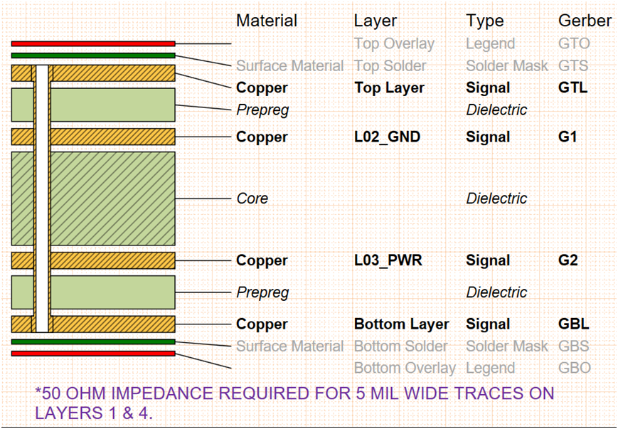
Advanced designs today often use HDI (High Density Interconnect) stacks with:
📌 Microvias — reduce stub and parasitic inductance
📌 VIPPO (Via In Pad Plated Over) — improves signal launch consistency
📌 Symmetric stackups — for mechanical/thermal stability
Materials with stable electrical profiles (PTFE, low Dk resins, Rogers laminates) make it possible to design controlled impedance layers for high speed signals while supporting HDI complexity.
For multiprotocol PCBs (5G, PCIe Gen6, CXL), impedance bands must be maintained within ±5% tolerance — a requirement driven by both material selection and fabrication precision.
8. Manufacturing Demands & Process Technologies
Manufacturing high frequency PCBs with these advanced materials presents challenges:
Surface Preparation
PTFE-based materials require special adhesion promotion for copper plating.
Precision Drilling & Microvia Formation
Very fine holes with controlled geometry are essential for stable SI performance.
Copper Plating
Uniform plating without voids ensures high reliability — a focus for any high frequency PCB manufacturer offering production services.
SMT/Assembly
Fine pitch components necessitate precise stencil design, controlled reflow profiles, and traceable BOMs.
Top-tier high frequency circuit board manufacturer and Rogers PCB manufacturer partners offer ODM one stop services including:
✔ Material selection consulting
✔ Stackup and SI/PI simulation
✔ Fabrication with HDI capabilities
✔ Full PCB assembly and validation
9. Reliability Engineering — Thermal, CAF, Moisture & Field Longevity
High frequency boards must endure harsh environments:
- Thermal cycling — material expansion presents reliability risk
- CAF (Conductive Anodic Filament) — moisture driven failure
- Vibration & shock — aerospace/UAV applications
Reliability regimes include:
✔ Thermal shock testing
✔ Highly accelerated stress testing (HAST)
✔ Long term aging
ODM partners often integrate reliability validation into their one stop services to meet industry standards.
10. Industry Applications — Where These Materials Excel
5G & mmWave Networks
PTFE and Rogers materials minimize loss at the high GHz bands required for beamforming and small cells.
Aerospace & Defense
Satellite comms, phased array radar, military radios rely on ultra stable, low loss materials.
Automobile Radar
Automotive radar at 77/79 GHz demands materials with extremely low dispersion and loss.
UAV & FPV Systems
Long distance video links and phased arrays in drones benefit from stable delay and low insertion loss.
High Speed Digital
Multi-gigabit SerDes channels are influenced by dielectric properties at tens of GHz.
11. Growing Market & Supplier Landscape
The rise of IoT, 5G, AI, and edge computing drives demand for high performance materials, creating opportunities for:
✅ High frequency PCB manufacturers consolidating a global supply chain
✅ ODM factories offering turnkey services from material selection to PCBA
✅ Strategic partnerships between designers and material vendors
Manufacturers who master the material science and supply chain integration will be positioned as market leaders across high frequency segments.
12. Future Material Trends — What's Next?
Emerging directions include:
📌 Nano engineered dielectrics with ultra low loss and stable Dk
📌 Liquid Crystal Polymer (LCP) for flexible RF systems
📌 Composite materials optimized for terahertz circuits
📌 Thermally conductive substrates for power dense applications
These innovations reflect an industry pushing toward even wider bandwidth, tighter tolerances, better manufacturability, and interoperability with digital RF convergence.
13. Materials as the Foundation of High Frequency PCBs
From component layers to aerospace systems, materials like PTFE, hybrids, and Rogers PCB laminates are essential. Whether you're working with high frequency circuit board manufacturer partners, choosing a high frequency PCB manufacturer, or integrating with an ODM one stop service, materials science sits at the core of every successful high performance PCB.
📣 Partner with Rich Full Joy for engineering driven material selection, controlled impedance design, and full ODM PCB manufacturing services — optimized for next generation RF, 5G, aerospace, and high speed applications.
14. Why do high frequency PCBs need special materials?
Because standard FR-4 has high Dk/Df, causing loss and reflection at GHz bands.
1. What's the difference between Rogers PCB and PTFE?
Rogers laminates are engineered resins with stable electric constants; PTFE offers even lower loss but is harder to process.
2. Why choose Rogers 4003 PCB?
Balanced performance/cost for 5G and microwave hardware.
3. When to use Rogers 5880 PCB?
For mmWave (>24 GHz) systems demanding ultra low loss and low Dk.
4. How does material affect SI/PI?
It determines impedance consistency and loss, directly impacting eye margin and jitter.
5. What manufacturing challenges do PTFE boards have?
Surface bonding and drilling require specialized processes.
6. Can low Dk resins be HDI compatible?
Yes — many HDI stackups use low Dk resins for combined performance and manufacturability.
7. Does material choice affect thermal reliability?
Yes — CTE matching prevents warpage and microvia fatigue.
8. Are these materials used in automotive radar?
Yes — material stability at mmWave is essential for 77/79 GHz systems.
9. What is an ODM one stop service?
A single provider handles design, material selection, fabrication, assembly, and test.
10. What's the supply risk for high freq materials?
Lead times and quality control are key; partnerships ensure consistency.
11. How to test delay and loss?
Using VNA, TDR, and SI simulation correlates with real measurements.
12. Why is HDI important for high frequency PCBs?
It reduces via length and parasitics for better signal performance.
13. What's the role of EMI shielding?
Materials with stable dielectric behavior minimize radiation and cross talk.
14. How to optimize stackup for signal timing?
Use symmetric layers and controlled dielectric constants for predictable propagation.