The Role of Rigid-Flex PCBs in Edge AI Devices: Enabling Smarter, Smaller, and More Robust Systems
Table of Contents
- Introduction
- The Engineering Imperative: Why Edge AI Demands a New PCB Paradigm
- Rigid-Flex PCBs: A Foundational Technology for Edge AI
- Real-World Applications: Where Rigid-Flex PCBs Enable Edge AI
- Designing with Rigid-Flex PCBs: A Professional's Guide
- The Future: Emerging Trends in Rigid-Flex for Edge AI
- Frequently Asked Questions (FAQ)
Introduction
The revolution in Edge Artificial Intelligence (AI) demands computational power not in the cloud, but within the devices themselves—from autonomous drones to smart sensors and AR glasses. This paradigm shift creates a fundamental engineering conflict: how to integrate powerful, complex electronics into increasingly small, lightweight, and unforgiving physical form factors. Traditional printed circuit board (PCB) architectures are hitting their limits. This article delves into why Rigid-Flex PCB technology has emerged as the unsung hero and a critical enabling technology for overcoming these barriers, allowing engineers to build the next wave of intelligent, compact, and durable Edge AI systems.
The Engineering Imperative: Why Edge AI Demands a New PCB Paradigm
Edge AI devices operate under a unique set of constraints that stretch traditional design methodologies to their breaking point.
The Core Design Dilemma: Performance vs. Form Factor
The central challenge is the "spatial conflict." High-performance Edge AI requires multiple components: a powerful System-on-Chip (SoC) with a Neural Processing Unit (NPU), high-bandwidth memory (e.g., LPDDR4/5), multiple sensors (cameras, LiDAR, IMUs), and RF modules. Housing these on multiple rigid boards connected by cables and connectors becomes prohibitively large, heavy, and fragile.
The Reliability Deficit of Connectors and Discrete Boards
In dynamic environments—such as a drone in flight, a robotic arm in motion, or a wearable on a person—connectors are primary failure points. Vibration, shock, and thermal cycling can lead to fretting corrosion, contact wear, and eventual disconnection, causing catastrophic failure for a device that is expected to operate autonomously.
Signal Integrity at the Edge: A Need for Speed and Precision
Edge AI processing is data-intensive. Signals from high-resolution image sensors or time-of-flight cameras must travel to the processor with minimal loss, reflection, or electromagnetic interference (EMI). Long, board-to-board cable runs act as antennas, degrading signal integrity and introducing noise that can compromise the accuracy of AI inference.
Rigid-Flex PCBs: A Foundational Technology for Edge AI
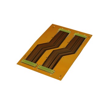
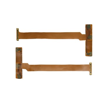
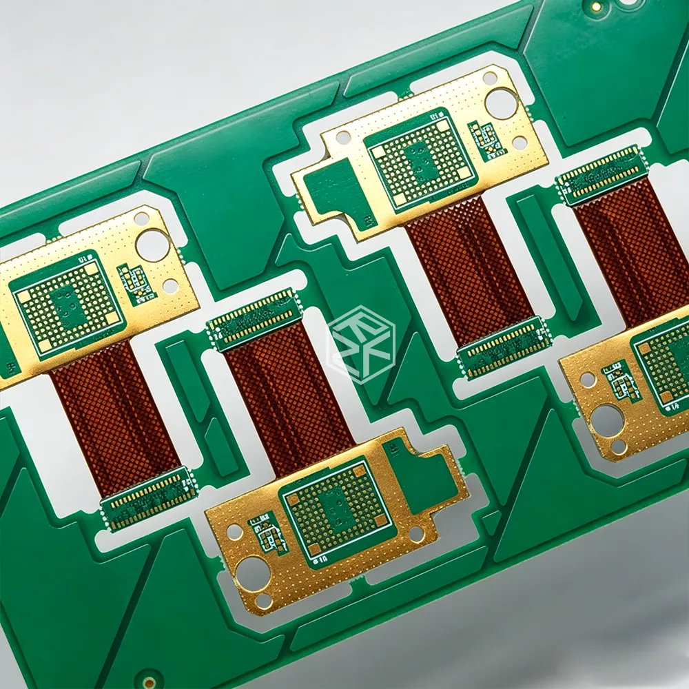
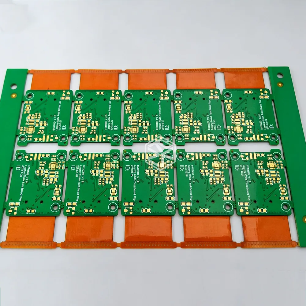
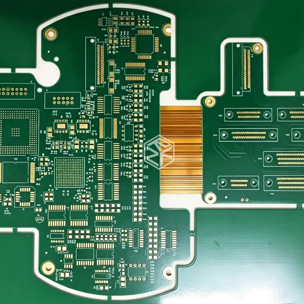
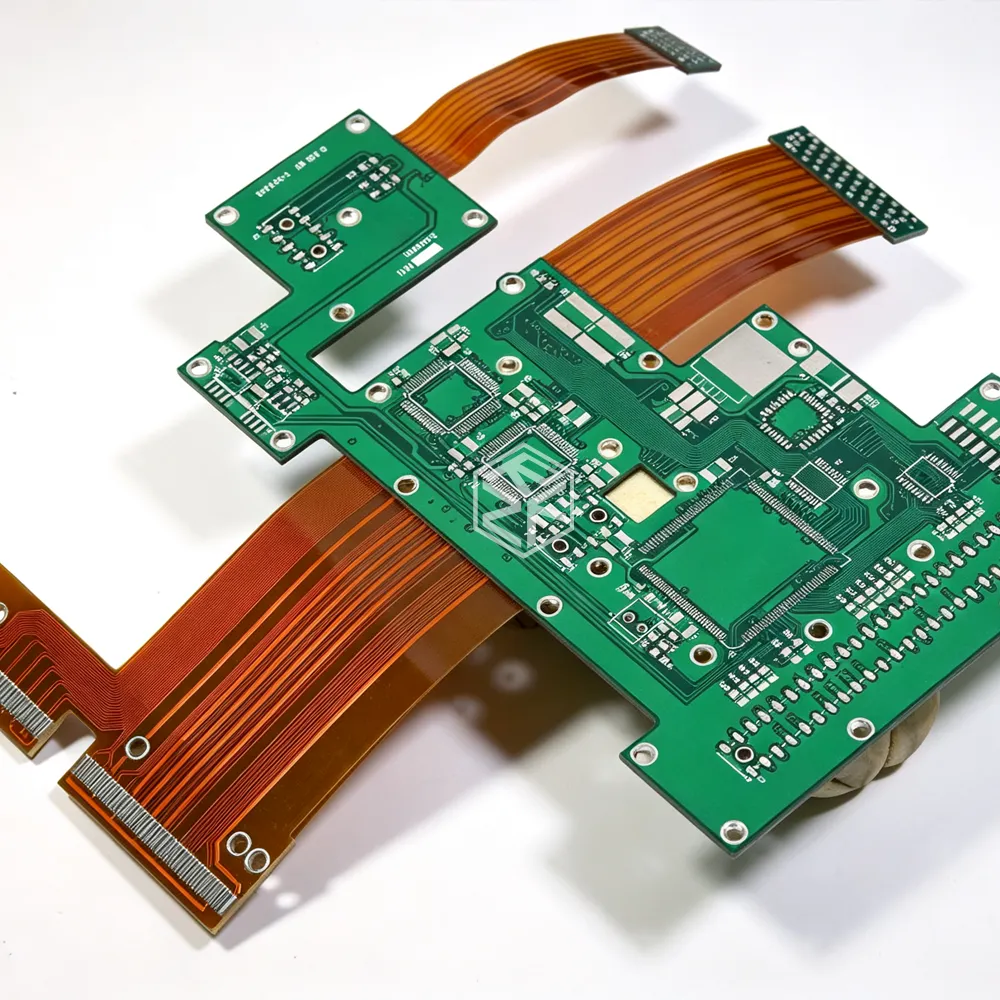
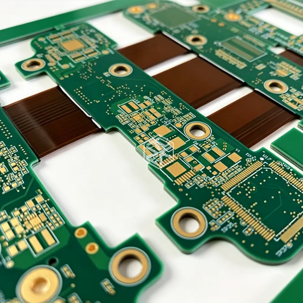
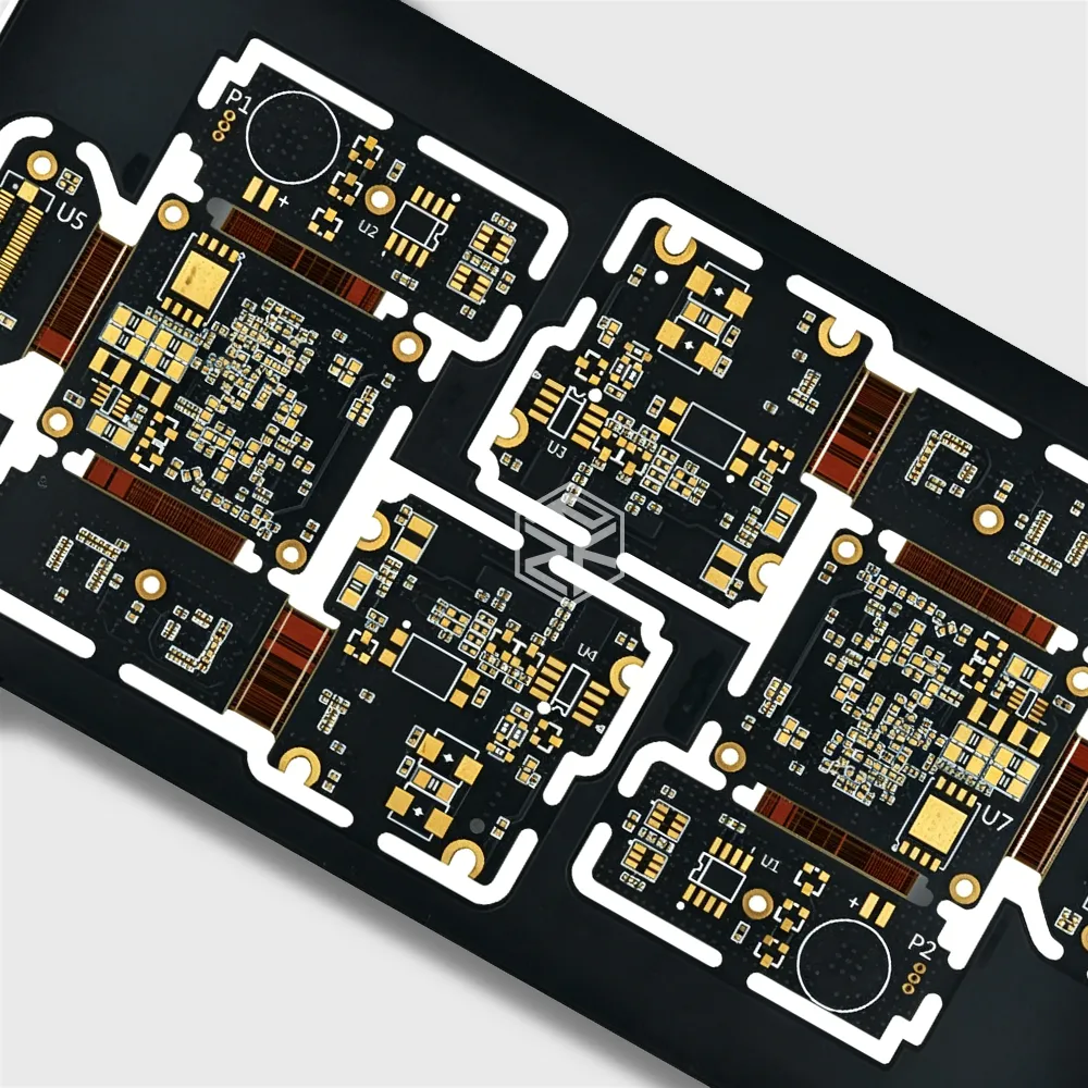
A Rigid-Flex PCB is a hybrid circuit board structure that integrates both rigid substrates (typically FR-4) for component mounting and flexible substrates (typically polyimide) for interconnections into a single, continuous unit.
Unmatched Space Efficiency and 3D Packaging Capabilities
This is the most significant advantage. The flexible sections allow the board to be folded or bent to fit into the ergonomic or aerodynamic contours of a device.
Example: In AR glasses, rigid sections host the micro-display and processor, while the flex sections snake around the frame to connect cameras and sensors, saving critical space and weight.
Enhanced Mechanical Reliability and Durability
By eliminating many board-to-board connectors and soldered cable assemblies, Rigid-Flex PCBs create a monolithic structure.
Benefit: This inherently improves resistance to shock, vibration, and mechanical fatigue. The flexible areas are designed for a specific bend radius, ensuring reliable performance over thousands of flex cycles.
Superior High-Speed Signal Integrity
Rigid-Flex designs enable shorter, more direct, and impedance-controlled pathways between critical components like sensors and the AI processor.
Technical Advantage: This results in reduced parasitic capacitance and inductance, lower crosstalk, and better EMI/EMC performance. This is non-negotiable for maintaining the integrity of high-speed serial interfaces like MIPI CSI-2, PCIe, and USB 3.0 common in Edge AI systems.
Improved Thermal and Weight Performance
The continuous polyimide layers can act as a pathway to dissipate heat away from high-power components like the SoC. Furthermore, the removal of connectors, cables, and additional board stiffeners leads to a significant reduction in overall system weight—a critical metric for drones and portable devices.
Real-World Applications: Where Rigid-Flex PCBs Enable Edge AI
Autonomous Drones and Robotics
Use Case: A single Rigid-Flex PCB can connect the flight controller (rigid), EO/IR cameras (rigid), and motor ESCs (rigid) through flexible circuits that navigate the drone's body. This saves space for a larger battery, reduces weight for longer flight time, and ensures reliability during aggressive maneuvers.
Advanced Wearables and Augmented Reality/Virtual Reality Headsets
Use Case: In a smartwatch, a Rigid-Flex can connect the mainboard to the display, heart rate monitor, and side buttons, allowing for a slimmer, waterproof design. In AR/VR headsets, they enable the compact, lightweight form factor essential for user comfort by linking multiple tracking cameras and displays to the central compute unit.
Industrial IoT and Predictive Maintenance Sensors
Use Case: Ruggedized sensors mounted on industrial machinery use Rigid-Flex PCBs to withstand constant vibration and harsh temperatures. The reliability of the single-board assembly ensures continuous data collection for vibration analysis and thermal monitoring, which is processed by on-device AI to predict failures.
Medical Diagnostic and Monitoring Devices
Use Case: Portable ultrasound probes and swallowable endoscopy pills use highly compact and reliable Rigid-Flex PCBs to connect transducer arrays and miniature cameras to processing logic, enabling new frontiers in portable and minimally invasive medical AI.
Designing with Rigid-Flex PCBs: A Professional's Guide
The Criticality of Early Collaboration
Successful Rigid-Flex design is not an afterthought. It requires early and deep collaboration between the product industrial designers, the mechanical engineers, and the PCB layout engineers to define the board outline, foldable areas, and bend radii in 3D space from the outset.
Navigating Manufacturing Complexity and Cost
Rigid-Flex PCBs have a higher initial cost and longer lead time than standard rigid boards due to complex lamination processes and specialized materials. However, the Total Cost of Ownership (TCO) is often lower when factoring in increased assembly yield, reduced part count (no connectors/cables), and superior field reliability.
Material Selection for Performance and Flex Endurance
- Standard Flex: Polyimide is the workhorse material.
- High-Frequency/Speed: Modified polyimide or Liquid Crystal Polymer (LCP) is chosen for their stable dielectric constant (Dk) and low loss tangent (Df), which are essential for multi-gigabit signals.
- High-Reliability Flex: Adhesiveless laminates are preferred for improved thermal performance and resistance to z-axis expansion.
The Future: Emerging Trends in Rigid-Flex for Edge AI
Integration Beyond Interconnection: Embedded Components
The next evolution involves embedding passive components (resistors, capacitors) and even active dies directly within the inner layers of the rigid or flexible sections. This saves surface area, shortens interconnects further, and enhances performance.
Stretchable Electronics and Conformable Devices
While Rigid-Flex circuits are flexible, research is advancing into truly stretchable electronics. This could lead to AI-powered epidermal patches that monitor health biomarkers or conformable sensors integrated into clothing.
Frequently Asked Questions (FAQ)
Q1: Are Rigid-Flex PCBs more expensive than traditional rigid PCBs with connectors?
Yes, the initial unit cost of a Rigid-Flex PCB is higher due to complex materials and manufacturing processes. However, a comprehensive cost analysis often reveals savings elsewhere: reduced bill of materials (no connectors/cables), simplified assembly, higher product reliability leading to lower warranty costs, and enabling a smaller, more competitive product form factor. The value is in the Total Cost of Ownership (TCO) and system-level performance gains.
Q2: How many bend cycles can a typical Rigid-Flex PCB withstand?
This is highly application-specific and is defined during design. We distinguish between:
- Static Bends: A one-time or infrequent bend during assembly. These can typically handle a bend radius as low as 10x the flex layer thickness.
- Dynamic Flexing: Continuous bending during device operation (e.g., a folding phone hinge). For these, designs aim for a larger bend radius (often >100x thickness) and use specific materials to endure from tens of thousands to over 1 million cycles. Your PCB fabricator will model and test this based on your requirements.
Q3: What are the key signal integrity considerations when designing a high-speed Rigid-Flex for Edge AI?
Key considerations include:
- Impedance Control: Maintaining consistent characteristic impedance (e.g., 50Ω single-ended, 100Ω differential) across the rigid-to-flex transitions is paramount. This requires precise control over dielectric thickness and trace geometry.
- Material Selection: Using low-loss flexible laminates (like LCP) for high-speed signals to minimize attenuation.
- Return Path Management: Ensuring an uninterrupted reference plane (ground) adjacent to critical signal traces, even through the flex regions, to control EMI and signal return currents.
Q4: Can Rigid-Flex PCBs be used in high-temperature environments common in some industrial AI applications?
Absolutely. Standard polyimide has a high Glass Transition Temperature (Tg) and is suitable for many industrial ranges. For extreme environments, high-performance polyimides or ceramic-filled PTFE composites can be used. The key is to discuss the operating temperature profile with your fabricator early in the design phase to select the appropriate materials and construction.
Q5: What is the most common mistake when designing a first Rigid-Flex board?
The most common mistake is treating it like a rigid board and involving the fabricator too late. Failing to model the 3D mechanical bending, specifying incorrect bend radii, and not adding tear stops or stiffeners in critical areas can lead to manufacturing delays and field failures. Engage a specialist Rigid-Flex PCB manufacturer during the conceptual design phase.