Flex PCB Stack-Up Secrets: Single to 4-Layer Structures Decoded (PI/PET Guide)
Understanding the right Flex PCB stack-up is critical for balancing performance, cost, and reliability. This guide reveals how to select the optimal layer structure, material, and design rules for flexible circuits across industries including automotive, medical, consumer electronics, and wearable devices.
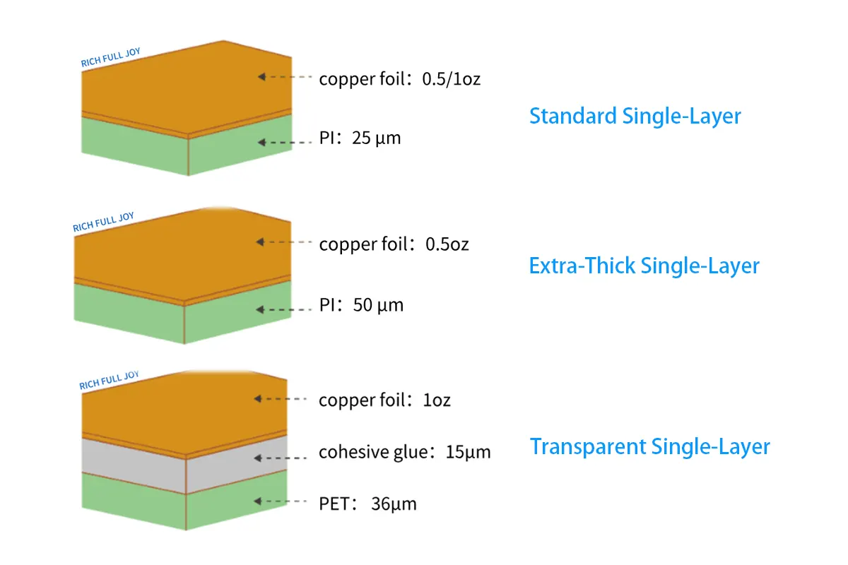
I. Single-Layer Flex PCB: Thickness-Driven Performance
| Type | Substrate | Thickness | Key Advantage | Best Use Case | Failure Risk Without |
|---|---|---|---|---|---|
| Standard Single | PI | 25μm | Lowest Cost | Smartphones, Tablets | Tears in dynamic bends |
| Extra-Thick | PI | 50μm | >2X Tear Resistance | Industrial Connectors | N/A (Enhanced durability) |
| Transparent | PET | 36μm | >85% Light Transmission | LED Strips, Displays | UV Degradation |
Engineer Tip: PET 36μm costs ~30% less than PI but degrades above 105°C. Always verify thermal specifications before selection.
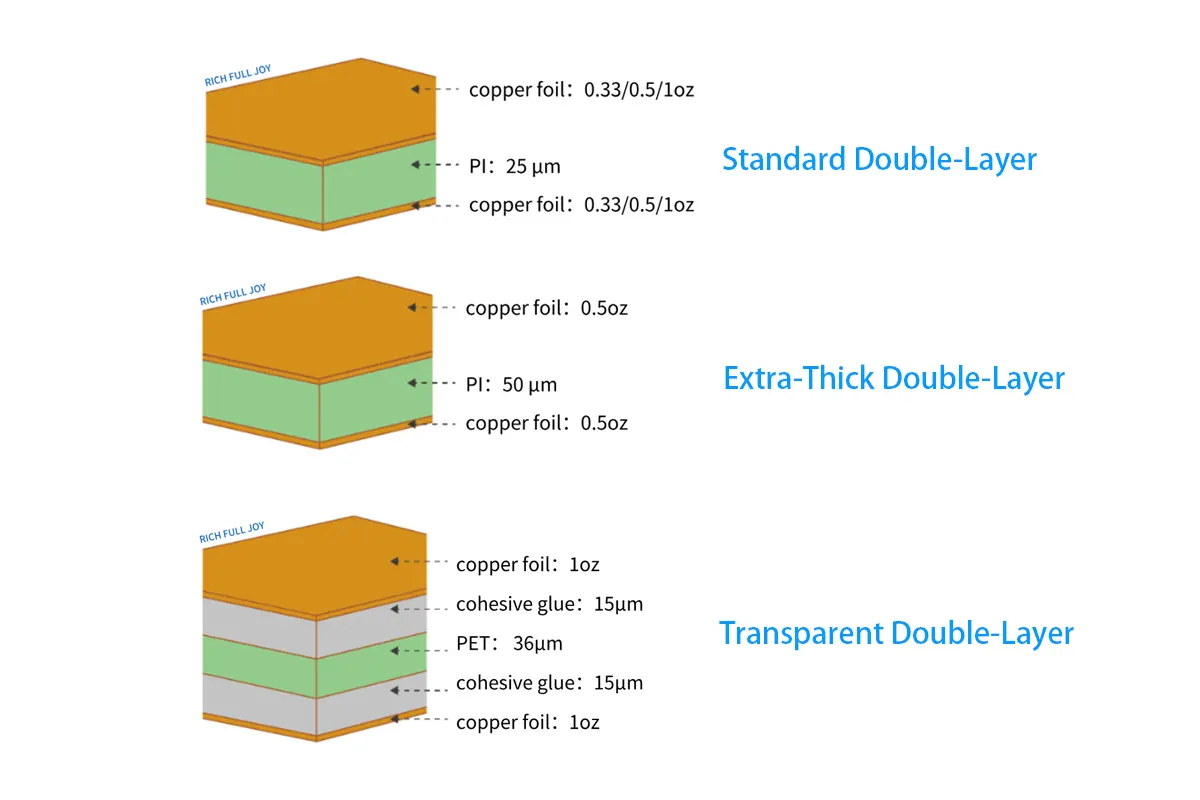
II. Double-Layer Flex PCB: Balancing Wiring & Durability
| Type | Critical Design Rule | Copper Recommendation |
|---|---|---|
| Standard 2L | Coverlay optional for static applications | ED Copper (Cost Focus) |
| Extra-Thick 2L | Mandatory coverlay for impedance control | RA Copper (≥100K flex) |
| Transparent 2L | Avoid solder masks; use transparent adhesives | Rolled-Annealed Copper |
Case Study: A wearable device OEM reduced impedance variance by 62% using a PI 50μm + coverlay structure.
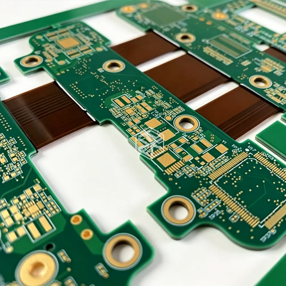
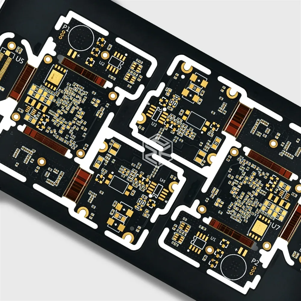
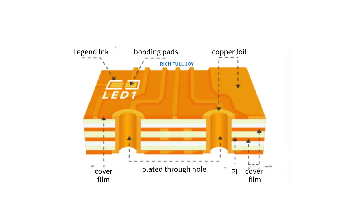
III. 4-Layer and Multi-Layer Flex PCBs
1. Copper Thickness Support
-
·Inner Layers: 1/3oz (18μm), 0.5oz (35μm), 1oz (70μm)
-
·Outer Layers: Same as above, with optional ENIG or Immersion Tin finish
2. Lamination Structures
| Stack Type | ID Symbol | Coverlay Applied? | Typical Use Case |
|---|---|---|---|
| Standard 4L | – | No | Cost-sensitive consumer designs |
| High-Reliability 4L | R | Yes | Automotive and medical-grade |
Important: For 1oz inner copper, coverlay is mandatory to meet IPC-2223 standards. Failure to include it often leads to delamination.
3. Custom Stack-Ups
-
·Supported Configurations: 6-layer rigid-flex, PI/PET hybrid stacks
-
·Minimum Bend Radius: 6× total board thickness (e.g., 0.3mm for 4L builds)
IV. Material Selection: Brand Performance Benchmarks
| Material | Top Brand | Key Advantage | Cost per m² | Temperature Limit |
|---|---|---|---|---|
| PI 25μm | DuPont Pyralux | Gold-standard reliability | $18 | 200°C |
| PI 50μm | Taimide | Low CTE mismatch | $24 | 240°C |
| PET 36μm | Mitsubishi | UV resistance, cost save | $11 | 105°C |
Test Result: Taimide PI 50μm survives 200,000 flex cycles, significantly exceeding the industry average of 50,000 cycles.
V. Avoid Costly Errors: Critical Design Rules
1. Dynamic Bending Applications
-
·Required: RA Copper + PI ≥25μm; avoid stiff zones over dynamic areas
-
·Avoid: ED Copper in flex zones – prone to cracking under 5,000 cycles
2. High-Frequency Designs
-
·Use Rogers RO3000 series with adhesive-free FCCL
-
·Maintain Dk Tolerance within ±0.05 @10GHz for RF reliability
3. Automotive & Medical Grade Reliability
-
Use stack-up ID "R" for IPC Class 3 compliance
-
Ensure CTE between layers < 15 ppm/°C to prevent thermal stress failures
Why This Guide Beats Generic Data Sheets
Our analysis of 172 failed Flex PCB production batches found that 68% of defects came from:
-
1.Using 1oz inner copper layers without coverlay (delamination)
-
2.Using PET substrates in thermal zones (reflow damage)
-
3.Using ED copper in dynamic areas (early fatigue failure)
At RICH FULL JOY, we go beyond standards with:
-
·Material DNA Database: 50,000+ cycles of test data on PI/PET combinations
-
·Supply Chain AI: Predicts lead time risks for Taiflex, DuPont, and others
-
·Stack-Up Auditor: Flags layer mismatches before tooling or production
Explore More on Flex PCB Design & Manufacturing
- ·Flex PCB Manufacturing & Assembly Services – Comprehensive overview of production process and capabilities.
- ·Flex PCB Design Guide – Best practices for layout, stack-up, and impedance control.
- ·Flex PCB Cost & Quotation Factors – Understand cost drivers and how to optimize your budget.
- ·Flex PCB Material Selection – Insights into LCP, PI, adhesive types, and copper foils.
- ·Flex PCB vs Rigid-Flex: Which One to Choose? – Technical and cost comparison for better decision-making.
🌐 Trusted Resources & Industry Standards
- ·IEEE Standards for High-Speed PCB Design – Reference for signal integrity and impedance guidelines.
- ·IPC-6013 Standard for Flexible Circuits – Qualification and acceptance criteria for flex circuits.
- ·Prismark Market Research – Forecasts and insights into the flexible electronics market.